


Model3490A
Be
sure
to connect
the
Guord
Terminal
and to obserye
the
maximum
voltage
limi-
tations
noted
on the
front
panel
and
in
Table 3-1
,
or damage
to
the
instrument
may
result.
3-58.
Input Connections
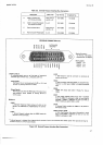
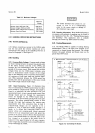
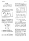
3-59.
Figure
3-3
shows
the proper
connections
for
making resistance
measurements.
All four terminals
must
be connected,
since there
is
no internal
connection
between
O
Signal
Low and Input
Low.
Maximum total
O
Signal
lead resistance
permissible
is 10 O.
O SIGNAL
Section
III
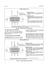
Rate
control
must
be set
to Hold,
or
a continuous
Low
signal
applied to
the Hold
connection
at
either
rear panel
connector.
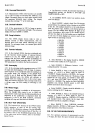
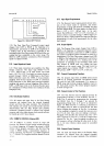
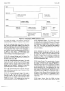
The
External
Encode
signal
logic levels
and
timing
requirements
are shown
in Figure
34.
The
High
to
Low
transition
of
External
Encode
and Data
Flae
can
occur
simultaneously.
HOLD
Pilä:::",----__1_
r
EXTERNAL
,
ENCODE
o
34904.81&
Tl
-
External
Encode
must be
HtLiH at
teast
16
ps
before
Data
Flag
goes
LOW.
This
requirement
rnay
be met
by
changing
External
Encode
to
HIGH
immediately
after
Data
Flag
goes
HIGH
indicating
the
start of a
measure-
ment
sequenoe.
T2-External
Encode
müSt
be HIGH for
at
least
4gps
before
it
goes
Low
to initiate
a measurement.
lf
External
Enmde
was
set HtGH
immediately
after Data
Flag
went
HIGH, the
T2 requirement
rnay
be
met
by
holding
External
Encode
HIGH until
Data
Flag
goes
LOW
indicating
completion
of
a measurement
sequence.
T3
-
External
Encode
must
rernain
LOW
for
at least
24O
ps
to
be accepted
and
initiate
a rEasurement.
T4
-
Data
Flag
will
go
HIGH
within
230
ps
of receipt
of a
valid
HIGH
to
LOW transition
of External
Enc,ode.
Figure
3-3.
Ohmmeter lnput
Connections.
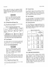
3-60. 0hms Signal
Voltage
and
Current.
3-61.
The
maximum
voltage
across the
resistance
being
measured
is 13
V for
valid
measurements
and 25
V
in
overload.
Table
3-4
lists the
approdmate
short
circuit
current
for each
range.
Accurate
voltage
and
current
sources
are not
required,
since
a resistance
measurement
is the
ratio
of
the voltage
across
the unknown
resistance
as a
result
of
the
reference
current, to
the
reference
voltage
which
determines
the
amount
of the currenr.
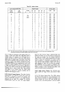
Table
34.
Ohmmeter
Current.
Range
Nominal
Current
.l
ko
lko
10
ko
100
ko
1,000
ko
10,000
ka
1mA
lmA
lmA
10
pA
10
pA
1
ttA
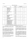
3-62.
0hmmeter
Sampte
Rate
and
Besponse Time.
3_-63.
Ohmmeter
sample
rates
and
response
times
are
shown
in
Table
3-2.
3-64.
EXTERNAL
TRtcGER
(Option
020).
365.
The
BCD/Remote
Expand
Option
020 adds
the
capability
of
remotely
rriggering
the
3490A through
either
the
Data
Output
or
Remote
Input
connector.
In
order
to
remotely
trigger
the
instrument,
the
Sample
Figure
3-4.
External
Trigger
Sequence
(Option
020).
3-66.
DATA
0UTPUT
(Option
021).
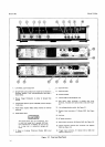
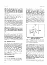
3-67.
The
Data
Output
option provides
ten
columns
of
measurement
data,
including
polarity,
range,
function,
and
overload
information.
A Data
Flag (prini
Commandj
output
is
also provided,
as
are inputs
for printer
hold
and
triggering.
Figure
2-5
shows
the
Data
Output
.
connector
and
signals.
A mating
connector,
-hp
part
No.
.
1251-0086
(Amphenol
No.
57-30500-375)
is supptied
"
with
Option
021
.
A
cable
terminated
at each .nä'by
u
50-pin
connector,
-hp-
562A-16C,
is
available
for
con-
nection
to
-hp-
digital
recorders.
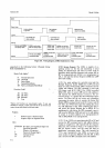
3-68.
Output
Signals
and Levels.
3-69. If
the
Model
3490{is
equipped
with
Data
Output
Option
02l
,Ien
columns
of l-24-8
coded
BCD
informa-
tion
are
provided,
In
addition
to
6 columns
of
measure-
ment
magnitude
information,
range,
function, polarity,
and
overload
information
are
provided.
The logic
HIGH
level
=
+
3.9
V r
1.5
V,
400
pA
max.
The
LOW
level
=0.3V
+
0.3V,
l5mA
max.
Columns
I
through
6
print
the
numerical
magnitude
of
a
measurement.
Figure
2-5
shows
the print
code
for columns
7 through
10,
using
a standard
-hp-
print
wheel,
+
or
-
124g.
The
HIGH/LOW
switch
on
the
Outguard
Data
Output
Assembly,
Al0,
must
be
set
to correspond
to
the logic
true
level
required
by the
digital
recorder
used.
Figure
3-5
shows
the printout
for
Option
021.
3-5