


:i
l
ii
j;
:l
.:'
a;
,'
.,1
,J
i
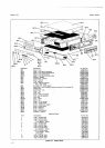
Model3490A
7.40.
DISPLAY
TRO
UBTESHOOTING.
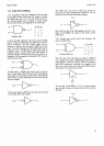
741.
"Ihe
Display
Troubleshooting
Tree, Figure 7-8,
mav
be
used
io
troubleshoot
a
defective
display'
The
nuäerical
display
units
and
the
polarity unit may
be
most
easily
checked
by
substituting
a known
good
unit'
Access
to
the
Display
Assembly
is
gained
by removing
the 3490A
top
trim
strip
and
the tfuee
vertical screws
securing
the
diiplay
heat
sink
to
the
guard shield'
742.
LOGIC
TBOUBLESHOOTING
SUGGESTIONS.
743. Several
microcircuits
in
the
logic section
may be
checked
by
observing
the
inputs and
outputs
of
the
device.
The
"Q"
output
of
a D
flip-flop, for example,
should
agree
with
the
"D"
input
if the
flipflop is
being
clocked.
(See
AlU6,
7,
71,
14, 17,20
md 22.) The
output
is changed
by
the
"0"
to
"1"
transition
of the
clock
input.
Also,
the output
of
an
inverter
(AlU8
and
10) should
be
the
logical
inverse
of its
input.
744.
lf incorrect
readings
are
observed on the logic test,
pull AlU2,
3,
9
and 16
and
reinstate,
taking care
to seat
leads
properly in their
sockets.
AlU2,3,
9 and 16
may
be
checked by substituting
a known
good
device.
'745.
Certain
microcircuits
may be
associated
with
particular
malfunctions.
A1Ul9
utd 2l deal with
pro-
gramming
the 3490A range
and function.
AlUl5
and24
are associated
with sampling and
sample
rate
delays.
AlUl5 also deals
with function delays.
746.
If
decimal
point
or ranging
problems
cannot
be
located by using
the
troubleshooting
trees,
the
trouble
may be
in
the display, the front
panel
switching, or the
optional Remote
Assembly. The
decimal
points
in
the
display are
switched
during the
LOW
true
enable signals
to the display units
(see
Figure
7-8).
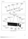
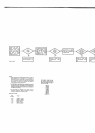
747.
If the instrument
does not sample, the logic
circuits may
be locked in
a
certain
state
or
sequence.
Turn the
instrument
off.
While
holding
the
manual
pushbutton
depressed,
turn the
instrument
back on anil.
observe the states
of
logic
signals
YMA through
YMG
with an
oscilloscope
(see
Figure
7-24).
These are
found
at
test points
O, T,
P,
S,
Q,
N
and
J
in
the logic section
of
,the
main circuit
board.
Test point
O
should
be a
steady
HIGH,
and
all others
LOW. If these levels
are.not
correct,
the
Read
Only
Memory,
AlU9, or one of the
State
Storage
flip-flops
may
be
defective.
If
all seven
sigrals
are
correct,
release
the pushbutton
and check the
test
points
again
with
the
oscilloscope.
If
all
levels
are
the same
as
before
(TPO
HIGH
and
all others
LOW),
the
normally closed
contacts
of
the
pushbutton
switch may
not
be making
contact.
Check to
see if the pushbutton is
binding in the
center
of the
Sample
Rate
knob.
7.48. DATA
OUTPUT
TROUBTESHOOTING
(0ption
021).
749.
Ceftan types
of failures
in
the
output information
may
be traced
to
certain
circuits
in the Data Output
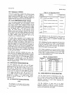
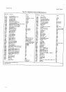
Assemblies.
Table
7-5
lists
a number
of svmptoms and
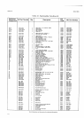
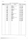
Section VII
Table
7-5.
Data
Output Troubleshooting
Tips.
Symptoms
Probablo
Cau$
Measurerent
Intotmatioo:
No data
output
No dab output and
no
polarity,
overload,
or overrange
No
odd numbers
in any
digit
No
2's,3's.6's,
or 7's in
any digit
No 4's,5's,6'!,
tr 7's in
any digit
No
8's
or
9's
in any
digit
Range
Intorrotion:
No range data output
No range and
no funcion
data output
No odd
numbered range
data
Ranges 2,3,
and 6
do not
print
correctly
Ranges 4,5,
and
6
do
not
print
correctly
Fundion lnformation:
No
{unction data
output
No tunction
and
no range output
Functions
1,
3, 5, 7,9,
-,
A, and
*
not correct
Functions 2,
3, 6. 7.
+,
-,
O, and
*
not correct
Functions4,5,
6,7,
V. A,
f|, and'
not correct
Functions 8,
9,
+,
-,
V, A,
O, and
i
not corrrct
Polaritv,
Overload,
Overrange. Sample/Hold,
and
Remote
Mode Intormtion:
None
of the
above
outputs correct
None oI
the
abow and
no
range output
No
polarity
output
No overload
outPJlt
No overrange
output
No Sample/Hold
Mode outPüt
No Remote
Mode
output
A9U9
A9U6
A10U1,2,3,7
A10U1
,2,4,7
A10U1,2,5,7
A10u1
,2,
6,7
AgU7
AgU6
41OU3
AlOU4
A1OU5
AgU7
A9U6
A1OU3
A1OU4
A1OU5
AlOU6
A9U7
AgU6
A1OUs
A1 OU6
A1OU3
AlOU6
A10U6
their probable
causes. Refer
also
to
the Data
Output
Troubleshooting
Tree, Figure
7-1
l.
7.50. REMOTE
CONTROL TROUBLESHOOTING
(0ption
022).
7-51. Refer
to the
Remote Troubleshooting
Tree,
Fig-
ure
7-12, for information
for troubleshootine
the
remote
control
circuits.
7-52.
cPlB
TROUBLESH00TtNc
(0ption
030).
7-53.
General Ghecks
7-54.
lf
the 34904
with Option
030 does not operate
correctly, first determine
whether
the trouble
is in the
I/O circuit
or the main 3490A circuits.
The performance
checks in
Section V may be used
to
determine whether
the instrument
operates
properly in standard
multimeter
operation. Make sure the
I/O
plug-in
printed
circuit
boards are seated
properly
in their sockets, and that the
ribbon cable
connectors
are inserted properly.
Also
make certain
that
all microcircuit
packages
are
seated
firmly in the sockets.
7-55. Troubleshooting Method.
7-56. The
logic circuits
which make up the GPIB
option
are very difficult
to troublestroot by the normal
compo-
nent method
of troubleshooting.
Consequently,
a GPIB
Repair Kit,
-hp-
Part No.
03490-80009, has been made
available
to facilitate
fast and efficient on-site
and bench
repair of
the GPIB
I/O Interface Option.
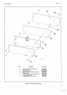
The GPIB
Repair
Kit
consists of five
assemblies
(*rp
Part
No.
0349G60613
,
46532,
-66533, -66534
and
-66536),
and
six
parts
kits
(hp
Part
No. 03490€0013, {0031,
-80032,
-80033, -80034
and
-80036),
which are indi-
vidually available.
See Table 6-1 for description of
assemblies
and
parts
kits. This table
also
provides
a
7-5