


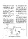
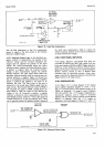
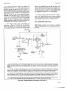

Model
34904
either
HIGH
or
LOW,
the
output is
LOW.
The HIGH/
LOW
switch
on
the Outguard Data
Output Assembly
controls
one
input
to each
gate.
When
the
HIGH/LOW
switch
is
set to
HIGH,
one input
to
each
gate
is
always
LOW;
consequently,
the
output
will
be the
same logic
level as
the
other
input.
When
the
switch
is set
to
LOW,
one
gate input
is
always
HIGH.
Consequently,
if
the
other input
is also
HIGH,
the
output
will
be LOW,
and if
the input is LOW,
the output
will
be HIGH.
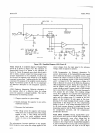
4170.
Data
Flag.
+171.
The
Data Flag output
signal
goes
HIGH
at the
begiruring
of a
measurement
and
LOW
after a reading
sequence
is
completed.
The
HIGH to
LOW transition
indicates
that
the
Data
Output information
is
ready.
This transition
constitutes
a
Print
Command to
a digital
recorder.
If the instrument
is
operating
in the
autorange
mode, Data Flag remains
HIGH until
a reading
on the
correct
range has been completed.
L172.
kinter Hold.
+173. A HIGH signal
from
a digital
recorder,
indicating
that the
recorder is not
ready
for
an input,
is inverted
and connected
to the
349OA
Hold line.
This
prevents
automatic sampling
until the
Printer
Hold
signal
returns
to
LOW. A slide
switch
on
the
Outguard
Data
Output
printed
circuit
board permits
disabling
of the
printer
Hold line. If
the
switch
is
in the
IN
position
and the
Printer
Hold
line is
left
open, the
inverting
transistor
output
may
go
LOW,
resulting
in
a
..Hold"
condition.
4t74.
REM0TE
C0NTR0t
0PTtoN
022.
+175.
The
Remote
Control
Option permits
remote
control
of
range,
function,
autorange
selection,
and
Sample/Hold
operation.
All connections
at the
rear
panel
Remote
Input
connector
are isolated
from
the
34g0{internal
circuits.
Power
to the
outguard
circuits
is
supplied
by the +
5
V outguard
power
supply.
Outguard
,r-.
ground
is
isolated
from
inguard
circuit common
and
from
chassis
(earth)
ground,
and
may
be floated
up to
40
V
above
chassis.
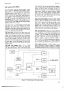
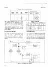
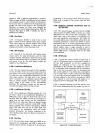
Figure
7-33
is a
diagram
of the
Remote
Control
circuits.
l}176.
Gircuit
lsolation.
1.177.
A photo-isolator,
consisting
of
a light-emitting
diode
which
drives
a photosensitivJtransistoi,
is
used to
carry
each
signal
across
guard.
Consequently,
there
is
no
electrical
connection
bätween
inguärd
and outguard
circuits.
4-178.
Remore
Enable.
4-179.
When
the
Remote
Enable
input
is
held
LOW
continuously,
this
information
is
carrieä
across the guard
to
the
bcal/Remote
FlipFlop.
Control
of the flif_flop
is provided
by
two
NAND
gates.
A
LOW
Remote Enable
signal
results
in
a
LOW
siglral
to
one
input
of
one of the
Section
IV
gates,
and
a HIGH signal
at one input
of
the
other
gate.
The
Remote
Enable
signal
is
gated
so
that
the
fwa[
Remote
Flip-Flop
cannot
be
changed
while
remote
program
information
is
being transferred
across guard.
4180.
0utguard
Multiplexer.
4181.
This
dual
4-to-1
line
multiplexer
accepts
g
bits
of
range
and
function
information.
Then,
when
a
progam
Execute
command
is given,
this
information
is
trans-
ferred
serially,
two
bits
at
a
time,
to the
two
inguard
Shift Registers.
The
Scan A signal
is
used
to
selecl
the
multiplexer
outputs.
ftan A is
applied
to
one
output
selection
line,
and
Scan
A divided
by
2
is
applied
toihe
other
line.
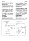
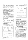
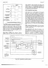
Figure
4-19
shows
the
multiplexer
output
sequence.
SEOUENTIAL
LOGIC INPUTS
PROGRAM
EXECUTE
H
scat{
c
SEOUENTIAL
LOGIC
-----_-I
OUTPUT
PROGRAM
FLAG
OUTPUT
I
I
ll
MULTIPLEXER
SELECT
INPUTS
I
ll
scaNA(So)
|
r---l
-
tlttl
SCAil A
+2
(S,}
r
<t
.,
:,'Ei
oUTGUARD
MULnpLEXER
i"
6:"
6i";lä
g
ourPurs
g!9!;?;Fi
rä,?rE
i,ä
,)ri
Sr
oara
cLocK
___:-_tt_tl_lt_lt__
ll
A[ R.hot.
doCroh
|
|
'nrdmoron
ronrt.'r.d
i
-
crd.
ouo.a öuri^o
!.sr.s
te.r
tht.
r.nod ot r,m.-
|
|
Figure
4-19.
Remote
Control
Timing
Diagram
(Option
022).
4182.
Remote
Sequential
Logic.
zl-183.
The
Sequential
Itgic
is
enabled
by
application
'-'of
a Program
Execute
command,
which
musf go
from
signal
is inverted
and applied
to
the
Logic. The
next
time
the
Scan
C
signal goes
LOW
after
receipt
of
a
progam
Execute
command,
the
Ingic
output
also
goes
LOW
and
remains
LOW
until
Scan
C
goes
HIGH. Inputs
to
the
JK
flip-flops
of the
Logic
are
gated
so that
only
one
LOW
output
is present
for
each
program
Execute
command,
regardless
of its pulse
width
above
5 ms.
While
the
Logic
output
is
LOW, it
enables
the
Data
Clock
signal
and the
Scan A signal,
so program
informa-
tion
may
be transferred
into
the shift
registers.
Also,
when
another
logic
output
signal
is
LOW, it
disables
a
gate
in
the
Remote
Enable
signal
line
so that
the
Iocal/Remote
selection
cannot
be changed
during the
Program
Execute
procedure.
+184.
Program
Flag.
4-185.
The Program
Flag signal
goes
HIGH to indicate
that
remote program
information
is
being
accepted,
and
+r9