


Section
IV
circuits, and is
dependent
upon the
sample rate switch
setting,
as well as the function
and range
selected. In
auto-range operation, the logic circuits
select
the
correct
range. The input polarity information
is
utilized by
the
logic
circuits
to select the correct reference
polarity
for
run-down.
415.
Display.
,1-16.
The
display
consists
of six digits;
however,
the
most significant
digit is
either
zero or
an
overrange
"1"
during
normal
measurements.
During
the
logic test
operation
(Test
No.
1),
other numbers are displayed
in
this dist. The
display
also contains a
polarity
symbol
and
an
"overload"
annunciator light. If the instrument
has
a Remote
Control
option, a
"REM"
annunciator
also
lights
*tren
remote
operation
is selected.
!.
Model3490A
4-17. Range and
Function
Control.
4-18. Range and function
may be selected by the front
panel
switches
or remotely,
if the
instrument
is equipped
with one of
the remote
control
options.
Remote
control
is
provided
by Option
022
paragraph
Ll74), or by the
General
Purpose
Interface Bus I/O
Option
030
(Para-
$aph4-196).
+19.
DC
ANAL0G CIRCUITS.
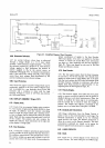
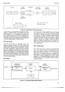
ar20.
In
general, the following
explanations of both
the
analog and digital
circuits
describe
the
circuits outlined
in the
block
diagram
shown
in
Figure
7-18.
421.
lnput Attenuator.
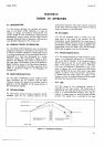
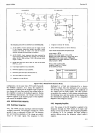
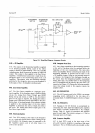
4-22.
A simplified diagam of the
Input Attenuator
and
DC Amplifier
circuits
is shown in Figure 4-3. The
Input
+REF
<
.REF
-{
oREF
{
ll
rl
ll
ll
oTrrrTzlzTr
tl
tl
tr
tz
oTr
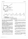
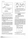
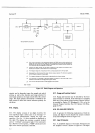
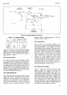
Prior ro the
run{p
portion
ot
the m@su.erent sequence,
the
3490A
inerts any
delay
requi.ed by
the
smple rate control
sening,
and
any
delav
rhat
may
be
required by
the fundion and range selections.
During
lhis time. the input to the DC Amplifier
is
grounded
and
this
amplifier
and the Integrator arc
in lhe
Auto-Zero
state
(see
Para$aphs 4-37 and 4-5O).
tTz
Following any delay required,
the
input signal
is
applied
to the
DC Amplifier
and sufficient
time is
allowed
lo. the
amplitier
to settle
belore
the run{p
period
begins.
2
T3
The I ntegrator charges tor a fi
xed
p6iod
of
ti me to a
rcltage
proponional
lo the input rignal
.
3Ta
Signal
pola.iry
is
determined and
the
prop€r
referen@ wltage is
plected-
The
relerence is
applied
to
rhe
DC Amplilier
in
plee
of
the input signal.
eTs
The
liltegrator
discharge. at a
tixed rate
which
is
determined
by the reference wltage.
sTo
ll the instrument is in
autoJange,
it
determin6 whether
the reading is
on
the @rrect range. It not, it
upranges or
downranges
ooe range aod.initiat€s another reading.
5Tq
This
is an Auto-Zero
period
of 65
ms.
(See
Paragfaphs
4-37 "nO
q-SO.l
s490
-
a-55!3
MEASUBEIVIENT
SEOUENCE
Ftgure
4-2.
Basic
Diagram and
Operation.