


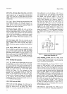
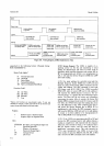
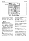

Model
3490A
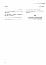
Figure 3-10.
Example
of Marked
Card
programming.
Section
III
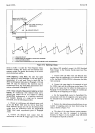
2. The
line
on the
marked
card immediately
fol-
lowing
the last
line
in
which
MRE is pulled
LOW
(,,200-
space
marked)
should
be left
blank.
This enables
the
3490A
to be
in the programming
routine
before the
first
programming
character
is
sent. If
this
line is
not
left
blank,
the character
on
that line
will be ignored.
3-139.
SAMPLE/H0LD
MEASUREMENTS
(0ption
040
or 045).
3-140.
Definition
of
Sample/Hold
Terms
3-141.
Track/Hold.
This
term
describes
the
mode
of
operation
in
which the
"Hold"
mode
(see
paragraph
3-14,
begins
within
400
nanoseconds
after receipt
oi a
Sample/Hold
Trigger
command.
Prior
to
this time,
the
Sample/Hold
amplifiers
follow,
or track, the
output
of
the
34904
DC
Input
Amplifier.
Upon
receipf
of
a
SampleiHold
Trigger
command,
the
amplifiers
..hold"
for
measurement
the
voltage
present
on the
Amplifier
A
integrating
capacitor
at that
time.
After
the
3490A
completes
a
measurement,
the
.track,'mode
resumes.
3-142.
Acquire/Hold.
This
mode
differs
from
the
Track/Hold
mode
in
that
a
precise
delay is
added
in the
Sample/Hold
trigger
path.
This
delay
allows
the DC
lnput
and
Sample/Hold
amplifiers
to
respond
to
a
full-range
step
input
voltage
before
the
Äold
mode
begins.
3-143.
Hold
Mode.
Following
a
Sample/Hold
Trigger
command,
the
Sample/Hold
AmplifierJ
A
and B retain
Ior
measurement
the
voltage
present
at Amplifier
A
when
the
Hold
command
was
received.
During this
retention
period.
the
Sample/Hold
amplifiers
are said to
be in
the
Hold
mode.
These
amplifiers
are
also placed
in
the
Hold
mode
during
the
run-down,
or
discharge,
portion
of the
measurement
cycle.
3-1u14.
Track
Mode.
After
completion
of
a
measure_
ment,
the
Sample/Hold
amplifiers
follow,
or
track,
the
input
voltage
until
they
are
placed
in
the
Hold
mode
by
a subsequent
Sample/Hold
Trigger
command.
This
con_
dition
is
referred
to
as the
Track
mode.
3-145.
Aperture
Time. This
is
defined
as the period
between
receipt
of a
Sample/Hold
Trigger
command
and
the
time
at
which the
Sample/Hold
switching
circuits
.place
Amplifier
A
in
the
Hold
mode.
F
3-146.
Maximum
Acquisition
Time.
This
is the
time
required
for the
DC
Input
and
Sample/Hold
amplifiers
to
respond
to
a full-range
step
input
voltage.
3-147.
Delay.
This
term,
as
used
in
connection
with
Acquire/Hold
operation,
refers
to the
delay
added
in
the
Sample/Hoid
trigger
path
which
extends
the
aperture
time
to include
the
acquisition
time.
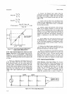
3-148.
Sample/Hold
Trigger
(TTL).
This is
the
dc
coup
led
command
to
the
Sample/Hold
circuits
which
initiates
a
Hold
mode.
The sigral
must
go
from
HIGH to
LOW
for
a minimum
of 30
nanoseconds.
It
must go
HIGH
at
least
600ps
prior
to going
LOW.
(See
Figure
2-l l.)
This
command
will initiate
a
3490A
measurement
only
under
certain
conditions
(see
Paragraph
3-165).
The term
"Sample/Hold
Trigger"
is
used
as
a
general
term
in
this
manua.l,
referring
either
to
a dc coupled
or
ac
coupled
trigger
signal.
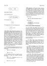
SEE
TABLE
3.7
BLANK LINE+
rffi'slisli
r.l.i...l*jiiä='8ffifr
lrrruE
349OA
PRoonnvr
],'ir
NO. )tEr
co0E
zoo rool40
zo
rol
+ z
I
I
iLEAR
27-l
r
Ei!
r rir
r
r
2C.C,
lfl
r
r alr
r
c=
3
EE
-I
E
El
=!n
E
c=
T ,21
C:I
06l
Etrf
r r
EIE
trf r
F toG
EI
6 0,60
--
E
r EIt:]
E [f
I
R t22
EI
-rtrlitrfIfl
9
4
o64
EE
r
r
c:lr
E r:
to
M t5
E=I
.EI
ll
I
06t
EE
tlcf
E:] ff
I
l?
E
to5
-}EE
IT:I
13
-l- -l-
UIUUU
--
3-l
5