


Model3490A
Section
IV
CLOCK
DATA
COUNTER
BUFFERS
EMITTER
FOLLOWER
TIMING
COUNTER
LTC
I
HJC
2
HTC
4
HTC
8
HTC
16
HTC
32
DCBA
TO
DISPLAY
AND
DATA
OUIPUT
STATE
CLOCK
OSCILLATOR
FREOUENCY
6OHz
LINE 4MHz
50Hz
LINE
3.333MH2
FOR
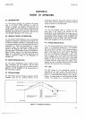
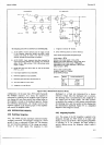
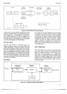
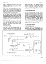
Figure 4-8.
Block Diagram,
Clock
and
Counters.
is derived
from
a Clock Oscillator
which drives
the
Data
Counter,
a
Timing
Counter, and the
State Clock. The
Clock Oscillator
is
a crystal-controlled
multivibrator.
The oscillator frequency is
4 MtIz in instruments
de-
signed for 60
Hz line
operation,
and 3.333
MHz in units
for 50 Hz operation. The
oscillator
output is
divided by
two
before being applied to
the Data
Counter.
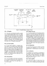
484. Data Gounter.
4{5.
The
Data
Counter is
a hexdecade
counter con-
taining
six
decade counters,
six
4line latches,
and
output multiplexing.
At the
end of
rundown,
a Transfer
pulse
from
the Transfer
and Zero Detect
logic transfers
the count
information
in
BCD
form into the
4-line
latches.
Scan signals
from
the Dsplay
assembly cause the
BCD
count information
to be transferred
to
the
Display
digit
by
digit,
beginning
with
the
least
significant
digit.
The
Data
Counter
accumulates
clock
pulses
continu-
ously
until
a Clear
Data
Counter
signal
is
received from
the
logic
Output
Decoder.
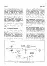
486.
Buffers
4€7.
Inputs
to
the buffer
amplifiers
are
two intermedi-
ate outputs
from the Data
Counter, Divide
by 10,000
and Divide
by
100,000.
The
outputs of these
amplifiers
are
gated
by
the
Select Hundred
Thousand
Counts
signals, HSHC
and LSHC, from
Logic
Storage.
If
HSHC
is HIGH
and LSHC is
LOW, the Divide
by
100,000
output
is selected,
and if
HSHC is
LOW
and
LSHC is
HIGH,
the Divide
by 10,000
output
is selected.
The
Buffer
output is
applied
through
an
emitter
follower
to
the
Timing
Counter.
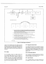
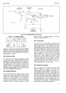
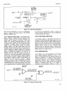
4-88. Timing
Counter.
4{9.
The Timing
Counter consists
of
a
single
D flip-flop
and
a 4-bit
binary counter.
Five
binary
square
wave
sigrals
are
produced
in
addition
to
the
Timing
Counter
input signal.
This
input signal
is not
a symmetrical
$quare
wave. but is
HIGH for
9,000
(or
90,000)
counts
and
LOW
for I
,000
(or
10,000)
counts.
These six
timing
signals
gö
to
the
Qualifier
Multiplexer,
and are used to
control
run-up
time,
overload
point,
sample
rate
delay,
and
function
delay.
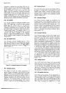
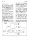
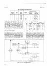
NEXT.STATE
PRESENT
FUNCTION
STATE
COMBINATIONAL
LOGIC
(GATES,
RoM,
etc.I
COMBINATIONAL
OUTPUT
LOGIC
INPUTS
OUTPUTS
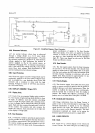
Figure
4-9. Typical
State
Machine
Block Diagram.
+9