


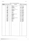
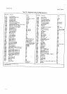

Section
VII
breakdown
of
individual
components
contained in the
Repair Kit and
their
respective
parts
kits. The
printed
circuit assemblies
provided
in the
repair kit may be
substituted
for assemblies
in
the
instrument in order
to
isolate the
trouble.
A kit
of microcircuit
packages
for
each assembly
is
provided
so that once the trouble
has
been
isolated
to
an
assembly,
the defective microcircuits
on that
assembly
may be replaced. A system controller
and a
printer
are
required
for troubleshooting the I/O
circuits.
These
may
be the controller and
printer
in
the
system
in
which the
3490A is
used.
A
dc voltmeter
is
also required.
The
GPIB Troubleshooting Tree, Figure
7-13, checks
most of the
3490A
I/O circuits.
7-57.
External
Trigger
Circuit Gheck.
7-58. The
external trigger circuits may be checked by
the following
procedure.
a.
Place 3490L
in local
control
by
setting the
Remote
Control Enable line
(LREN)
to
HIGH.
b.
Set
front
panel
SAMPLE
RATE control to HOLD.
Check
logic level
of
External
Trigger
Flag
(LETF)
at
Jl
I
pin 4.
Measure
to outguard
ground
at
pin
8 or
14
of
Jl l,
or on Outguard Data Assembly A33. LETF should be
LOW until an external trigger
command is
given.
If
not,
check
A31Ql.
c. Momentarily connect
Jl l pin
7 to
outguard
ground.
349OA should sample
each time
pin
7 is
grounded.
If
not,
check
A3lQ2 and associated compo-
nents,
including
pulse
transformer Tl.
If
the instrument
does
not have the
Sample/Hold
option, a
jumper
should
be
installed in
place
of
Tl.
Make sure this
jumper
is.
seated
properly
in the correct sockets.
7.59. SAMPLE/HOLD
SERVICING.
7-60.
Acces
to
Sample/Hold Gircuits.
7-61.
The
Sample/Hold
Analog and
Logic
printed
cir-
cuit
assemblies, A27 and A28, are fastened together
and,
must be removed from
their sockets as a unit. Printed
circuit
extender
boards
(Part
Nos. 5060-6032
and
5060-5983,
supplied
with the 3490A
Option 040/045)
may
be used to
mount the Sample/Hold
assemblies high
enough
for
access to the circuits.
The metal shield
covering
the
Logic assembly may
be
removed without
separating
the
two
assemblies. Do not
separate
these
assemblies
unless it
becomes necessary in order to
replace
components.
The
Analog
Assembly,
A2T,especially
those
oreas
in the
vicinit)'
of the teflon insulators,
must
be
kept
cleon
and
free
from ftnger-
prints
or
other
contamination,
or Samplef
Hold
performsnce
m6v
be degraded.
Model3490A
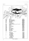
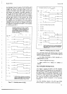
742. lt
it
becomes
necessary
to
separate the
Sample/
Hold
printed
circuit assemblies
in order
to
replace
certain
components, it
is
preferable not to disassemble
more than necessary. For
example,
if a repair is to
be
made
to
the
Analog
Assembly,
A21,the
flexible shield
should not
be removed
from
A28.
If the unit
has been
disassembled,
use the following
procedure
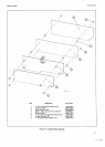
and Figure
7-3 for reassembly.
a. Place
Logic Assembly
A28
(item
3 in
Figure
7-3)
component
side
down
on work
surface.
Place
4
spacers
(item
4) over
the four
captive spacers
in L28.
b.
Carefully
put flexible shield in
place,
aligning
holes in shield
with the
spacers.
c.
Secure shield to A28, using
two nylon
screws
(item
6) in the two holes nearest the bottom edge of
A28.These screws
must be non-metallic.
d. Place two spacers
(item
4) on
top of
the
other
two
holes
in flexible shield.
e.
Place
Analog Assembly,
A27,
component side
up
over
the two spacers in
step
d and
secure with the screws
(item
8).
f. Secure aluminum
shield
(item
2)
over component
side
of
A28,
using four
screws
(item
l).
g.
Connect brown,
red
and
orange wires
from
A28 to
pins
l, 2 and 3,
respectively, on A27
.
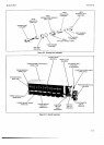
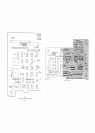
7-63. 0perating
the 3490A
with Sample/Hold
Assem-
hlies
Removed.
7-64.
lf
a
problem exists in the
Sample/Hold
circuits
which
affects
operation
of the 3490A with Sample/Hold
off, the
S/H
Analog and
Logic Assemblies, A21 and
A28,
may be
removed and replaced by
jumper
boards,
which are
supplied
with
the Sample/Hold
option.
These
boards
complete
the circuits necessary to allow
the
3490A
to operate
(see
Figure 4-27). The
wire discon-
nected
from
the
Analog assembly must be
connected to
the
pin on
the
Analog Jumper Board for
proper
operation.
Five
pins
are also
provided
at
the left end of
the Logic
Jumper
Board
for
terminating the
wires
disconnected
from
the
Logic assembly.
These
pins
are
not
connected
to any
circuitry.
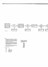
7.65. SAMPTE/HOLD
TROUBLESHOOTING
TREES.
l-66.
Two
troubleshooting
trees
are
provided
to assist in
isolating
problems
in instruments with Sample/Hold.
The S/H
General
Troubleshooting Tree,
Figure
7-14,
is
designed
to
determine
if the trouble is in
the
Sample/
Hold
circuits
or
in
other
circuits
in the 3490A.
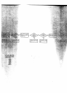
If
it is
determined
that
the
trouble is
indeed in the
Samplei
Hold
circuits,
this
tree
will
also
help determine
whether
it is in
the analog
or logic
circuits.
The Logic Trouble-
shooting
Tree,
Figure 7-15, provides further assistance in
isolating
trouble
in
the
Sample/Hold
logic circuits.
74