


Section
VII
7.67.
RATIO
TBOUBLESHOOTING.
l-68.
If ratio
measurements
are not
correct
and the
trouble
cannot
be corrected
by the
Adjustment
proce_
dure,
or if
the adjustments
cannot
be
made
correctlv.
the
following
troubleshooting
information
should
be
used.
Check
for obvious
sources
of
trouble,
such
as
burned
or loose
components
or
loose
wires.
Make
sure
the printed
circuit
board,
Al3,
is
seated
firmly
in its
connector,
and that
the
cable,
W8,
and
the
three
operational
amplifiers
are seated
firmly
in
their
sockets.
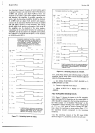
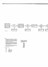
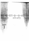
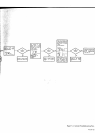
7-69. External
Reference
Amplifier
Checks
7-70.
The
Ratio
Troubleshooting
Tree,
Figure
7_16,
checks
the
External
Reference
Amplifier
circuits.
How_
ever,
correct
interpretation
of
the
display
symptoms
is
needed
to
determine
if
the
trouble
is
in the
ämphner
or
logic
circuits.
For
example,
if
the
display
reads
approxi_
mately
75%
of
normal (l0V
Input/tOV
Exi.
nef.
=
07.5000),
the
trouble
is
probably
in
the
amplifier
circuits.
If
the
display
reads
Overload
for
both
positive
and
negative
inputs (at
INPUT
terminals),
the
trouble
is
probably
in
the
amplifier
circuits,
but
if
it
reads
Overload
for
only
one
input polarity,
the trouble
is more
likely
in the
logic
circuits.
If
the
displayed
polarity
is
incorrect
and
the
display
reads
Overload,
check
the
polarit
y
logic
circuits.
7-71.
Amplifier
Zerc
0ffset.
7-12.
lf
the
Reference
Amplifier
zero
adiustments
in
steps
a through
h
of the
Ratio
Adjustment
procedure
cannot
be
made
correctly,
the
trouble
may
be leakage
in
either
AI3CR2
or
3. This
condition
can
be most
easily
checked
by
unsoldering
one
lead
of
each
diode
and
trying
the
zero procedure
again.
If
the
amplifiers
can
6e
zeroed
with
the
diodes
disconnected,
one
or
both
of
them
is
defective.
7-73.
Reference
Polarity
Logic
Checks
7-74.
ln
the
3490A
measurement
system,
if the
Input
voltage
is positive,
a negative
reference
is
required
ior
run-down,
and
vice
versa.
In
ratio
measurements,
the
applied
External
Reference
voltage
is
inverted
and these
two
voltages
are substituted
for
the positive
and negative
intemal
reference
voltages.
The
Reference
polarity
Logic
on
the
Ratio
Assembly,
A13,
makes
it
possible
to
use
either
polarity
Externai
Reference
inp,lt
,itt
.itt
u
polarity
Input
voltage
by
selecting
the
öorrect
reference
polarity
for
rundown.
If
a
failure
in
the
Reference
Polarity
Logic
causes
the
reference
voltaqe
used
for
run{own
to
be
the
same
polarity
as
the
Input,
the
display
will
indicate
Overloäd.
If
the
3490A
operares
correctly
in
dc voltage
measurements
with inputs
of
both
polarities.
but
reads
Overload
with
one polarity
input
in
ratio
measurements,
check
the
Reference
Polaritl'
Logic
as
follows
:
a-
Set
R{TIO
switch
to
EXT
REF
l0Vandapply
l0 \'to
EXT
REF
terminals.
--]
Model34904
b.
Set FUNCTION
to
DC and
apply
full-range
input
on
either
the
1
V or l0 V
range.
Select the
combination
of
INPUT
and
EXT
REF
polarity
that
causes
the
display
to
read
Overload.
c.
Set
SAMPLE
RATE to
HOLD.
Check
logic
levels
within
Reference
Polarity
Logic circuits
as
indicated
on
the
schematic
diagram, Figure
j-22.
Losic
HIGH
=
+
2.4V
to
+
5 V. LOW
=
0 to
+
0.6
V.
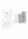
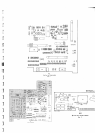
7.75.
SCHEMATIC
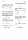
NOTES.
7-76.
tll.e
following
notes
apply
in general
to
all
schematic
diagrams:
a.
Partial
reference
designations
are
shown.
prefix
with
asembly
or subassembly
desigration(s)
or
both
for
complete
designation.
b.
Component
values
are
shown
as follows
unless
otherwise
noted:
Capacitance
in
microfarads
Resistance
in
ohms
c.
*
Average
value
shown.
Optimum
value
selected
at
factory.
I
d.
=
Denotes
earth ground.
e.
I Denotes
chassis
or
frame
ground.
f.
f
Denotes
floatable
circuit
ground.
.9.
qP
Denotes
printed
circuit
assembly ground.
-V
k.
Denotes
assembly
outline.
Denotes
subassembly
out-
line.
Denotes
main
sigral
path.
Denotes
feedback
path.
l.
l------l
Denotes
front
panel
markings.
Denotes
screwdriver
adjust.
n.Wl Denotes
wire
color.
Color
code
is the
same
as
the
resistor
color
code.
First
number
identifies
the
base
color;
second
identifies
the wider
strip;
and third
number
identifies
the narrower
strip (e.g.
924
=
white,
red,
yellow).
"
3
Denotes
schematic
number
on
which
con-
Y
nection
is
maije.
p.
A
Refer
to
manual
backdating,
Section
VIII.