


Model3490A
SECTION
INSTATI.ATION AN
D
Section
II
tl
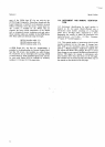
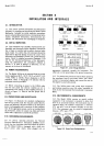
INTERFACE
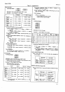
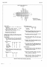
Figure
2-1
. Line Voltage
Selection.
appropriate
receptacle,
grounds
the
instrument.
The
offset pin
on the
power
plug
is the
ground
connection.
2-12.
To preserve
the protection
feature
when
operating
the
instrument
from
a two+ontact
outlet,
use a three-
contact
to
two-contact
adapter
and connect
the
wire on
the
adapter
to power-line ground.
2-13.
The 349OA power
cord, power
input
receptacle
and
mating
connectors
meet
the safety
standards
set
forth
by the Intemational
Electrotechnical
Commission
,(rEc).
2.14.
ENVIRONMENTAL
REOUIREMENTS.
2-15. The
Model 3490A
requires no special
cooling
equipment
if the
instrument is
mounted
to allow
free
flow
of air
around
all
surfaces.
The instrument
may be
operated
where
the
ambient temperature
is
between
0o
C and 40o
C
and the
relative humidity
is less than
95
%.
The instrument
may
be stored at temperatures
between
-
20o
C
and
+
75o
C.
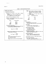
8r20-1689
8t20-r369
8120-t35t
8t20-r348
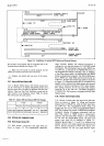
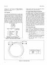
"'i,nur"
2-2. Powercord
Gonfigurations.
2.r.
|NTR0Dt
CTloN.
2-2.
This
section contains
information
and
instructions
necessary
for
installing and
interfacing
the
Model 3490A
Multimeter.
Included
are initial inspection
procedures,
power
and
grounding
requirements, environmental
infor-
mation,
installation
instructions,
interconnection
pro-
cedures,
and
instructions
for
repackaging
for shipment.
2.3.
INITIAL
INSPECTION.
2-4. This
instrument
was carefully inspected
both me-
chanically and electrically
before shipment.
It should
be
free of mars or scratches
and in
perfect
electrical
order
upon
receipt. To confirm this,
the instrument
should
be
inspected
for
physical
damage incurred
in
transit.
If the
instrument
was damaged in transit,
file
a claim
with the
carrier.
Check
for
supplied
accessories
@aragraph
1-10)
and test the
electrical performance
of the
instrument
using the performance
test procedures
outlined
in
Section V. If
there is
damage or
deficiency, see
the
warranty
in
the front
of this
manual.
2.5. POWEB
REOUIREMENTS.
24. T\e
Model 3490A
can
be
operated
from
any
power
source
supplying
100
V,
l2OV,
220
Y or 24O
V
(-
l0
%
+
5V),48H2
to 44OHz.
Power
dissipation
is
60VA
maximum.
Refer
to Paragraph
3-18
(Section
III)
for
instrument
tum-on procedure.
2-7.
Before
connecting
ac
power
to
the
3490A,
make
sure
the
rear panel
line
selector
switches
are set to
correspond
to
the
voltage
of
the available power
line
as
shown
in
Figure
2-l
. Also,
be sure
the proper
fuse
is
installed.
2.8. POWER
CORDS
AND
RECEPTACLES.
2-9.
Figure
2-2
illustrates
the
standard
configurations
used
for
-hp-
power
cords. The
-hp-
part
number
directly
above
each
drawing
is the part
number
for an instrument
power
cord
equipped
with
a connector
of
that configura-
tion.
If
the
appropriate
power
cord is not included
with
the
instrument,
notify
the
nearest
-hp-
Sales
and
Service
Office
and
a replacement
cord
will be
provided.
2.1
(|.
GROUNDING
REOUIR
EMENTS.
2-11.
To protect
operating
personnel,
the
National
Electrical
Manufacturer's
Association
(NEMA)
recom-
mends
that
the
instrument
panel
and cabinet
be
ground-
ed.
The
Model
34904
is equipped
with
a
three
con-
ductor
power
cable
which,
when
plugged
into an
r-
IOOV--r
I r-r
20v-l
ilil
I
Lzqov----l
\-22OV
'
IOO
Volts
r-
l@V-
I a
rzov-l
ilE
I
L
zqov--]
L
220V
'-
220
Volls
-1O%,+
5% of
nominal
90 to 105
volts
108
to 1 26 volts
198 to
231 volrs
216 to
252
volrs
@
ffi
W
sT0
2-1