


Table of Contents
Model 34904
LIST
OF
ILLUSTBATIONS
Figure
Page
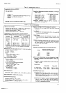
2-1 . Line Voltage Selection . . .2-l
2-2.
PowerCordConfigurations .... .......2-l
2-3. Model3490ADimensions ......2-2
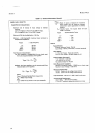
24. Installation of
Isolated
BCD
Output
and
Remote
Options
.
. .. . .. .2-3
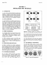
2-5.
Data OutputConnections, Option 021 ........24
2-6. Remote
Input
Connections, Option
022 ...
. .
. . 2-5
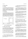
2-7. RearlnputConnectorandCable .......2-6
2-8. Interface Bus Cables
. . . .2-6
2-9. General
Purpose Interface Bus
Connections. . . . .2-J
2-10. Tigger Connections, GPIB Option 030 . . .. . .
. .2-8
2-l I . Trigger Connections
S/H Option
045 . . . -
. .
.
. . .
2-8
3-1. Front and
Rear
Panel
. . . . 3-0
3-2. Connecting the Guard .
. .3-2
3-3.
OhmmeterlnputConnections . ........3-5
34. External Trigger
Sequence
(Option
020) ...
. .. . 3-5
3-5. Option
021
Printout .
. . .3-6
3-6. Remote Program
Sequence
(Option
022) . . . .
.
.3-7
3-7 . Position of Jumper
Wires on Outguard
Mother
Board
Assemblv A31
3-8. Timing Diagram,
3490A
Addressed
to
Listen . . 3-l I
3-9.
Timing Diagram, 3490A
Addressed
to Talk
. . . .3-12
3-10.
Example ofMarked CardProgramming
. . . . . .. 3-15
3-1 l. Typical Response to
a
Step
InputVoltage....
..3-18
3-12.
Di$tizingaRamp
.....3-19
3-13. Using Delayed-Sweep
Oscilloscope
in
RampLinearityMeasurements
. . ...3-20
3-14. Filter
Output Measurement
. . . .3-2O
3-l 5.
Measurement
of a Step
Input
.
.
. 3-21
3-16.
RatiolnputConnections.
.....3-21
4-1
. Dual-SlopeIntegration
...4-1
Figure
Page
4-23.
Waveforms
Illustrating
Acquire/HoldMode.
......4-22
4-24.
Simplified
Diagram
and
Operationof
S/HCircuit
A..
..
....4-23
4-25.
Simplified Diagram
of
S/H
Circuit
B . . . . .. ..
.4-24
4-26.
Aebctric
Absorption
Compensation .
. .
.
. . -
. .
4-25
4-27.
Sample/Hole
Logic Block Diagram .. .
....
. . .
4-25
4-28. Block
Diagram
of
S/H Timing
andTriggerCircuits
.......4-26
4-29.
Sample/Hold
Trigger Timing . . .4-26
4-30.
Sample/HoldMeasurement
Sequence
..
..
-...+28
4-31.
Sample/Hold
Simplified Diagram
and
Measurement
Sequence
....+29
5-1.
AC Voltmeter
High Frequency
AccuracyTest..
.....5-2
5-2. DCCommon-Mode
RejectionTest
.....5-3
5-3. AC
Common-Mode
Rejection Test . .
. .
.54
54.
ACNormal-Mode
RejectionTest .. ..... 5-5
5-5.
DCVoltmeterlnput
Resistance Test ..
. . . . .. .
. 5-5
5-6.
ACVoltmeter Input Impedance Test
.
... . .....
5-6
5-7.
Sample/Hold Response Test .
-
. .5-7
5-8. External
Reference
Input
ResistanceTest.. ....5-9
5-9.
Location
of
Adjustments,
Standard3490A
....5-14
5-10.
Location of
Sample/HoldAdjustments
..
.....5-17
5-ll.
Location of Ratio Adjustments
.......5-18
6-1. ChassisParts
.
..6-30
G2. BindingPost
Assembly
....
...6-31
6-3.
SwitchAssembly
......G31
7-1.
Switching
Inputs to A2U2 .
.
..
. .7-3
7-2.
SwitchingOutputsofAlU4Ol
........1-3
3-8
4-2. BasicDiagramandOperation.....
.....1"2
.:7-3. Sample/HoldAssembly
........7-7
4-3.
SimplifiedDiagram,DCAmplifier
......4-3
14.
deneralTroubleshootingTree
....7-ll17-12
44.
Measurement
Sequence
.. . ... -
.44
iL'
l-5.
DC Ana1os Troubleshootins
Tree .]-1317-14
4-5.
Simplified Diagram,
Integrator Circuits . . . . - . . . 4-6
j
4. AC Conveiter
Troubleshooling Tree
.
.
. . .
i,-1511-16
4-6.
Simplified Diagram,
AC Converter
. .
.
.
.
. . .
.
.
. .4-7
7-7 . Ohms Converter Troubleshooting
Tree . . .7-17
17-18
4-1.
SimplifiedDiagram,OhmsConverter..........4-8
7-9. DisplayTroubleshootingTree
....|.-1917-20
4-8. Block
Diagram,
Clock and
Counters .
.
.
.4-9
j-9.
Loeic Test Troubleshooting
Tree
.
.7-21
17-22
4-9. TypicalStateMachineBlockDiagram
...4-g
7-tO. I_ofibClockTroubleshooti"ngTree.......l-2317-24
4-10. Block Diagram,
Main
Logic
7-l l. Data
Output
Troubleshooting
Tree
ASMFlowChart.
...4-10
option}2l
..
..1-2517-26
4-l l. Block
Diagram,
Main
Logic
Circuits . . . .4-11
7-12. Remote Troubleshooting
Tree,
4-12. Block Diagram,
Qualifier
Multiplexer
. .4-12
option
022
.
.
. .i-2717-28
4-13.
Simplified Diagram, Reference
7-13.
GPIB
I/O
Troubleshooting
Tree,
and Ratio
Circuits . . .4-13
Option 030
. .
.
.7-2917-30
4-14.
Simplified Diagram, External
7-14.
Sample/Hold
General Troubleshooting
Reference
Circuits
.
.
4-14
Tree . .
.1-31
17-32
4-15. Input Bias
Compensation
. .
. . .
.4-15
7-1
5.
Sample/Hold
Logic
Troubleshooting
4-16. ReferencePolarityLogic.
.....4-15
Tree ..
.1-3317-34
4-17.
PowerSupplyBlockDiagram
...
.....4-16
7-16. RatioTroubleshootingTree
....7-35
418. DataOutputTimingDiagram(Option02l)
...4-18
7-17. Locationof Assemblies
...
....7-36
4-19. Remote
Control
Timing Diagram 7-18.
3490A Block
Diagram
. .7-37
(Option
022)
. .....4-19 7-19. Reference Desigrations
.. .....7-38
4-20. T1'pical
Bus
System
. . . .4-20
7-20. Schematic
Diagram,
DC Amplifier
4-31. SampleiHold
Circuir Position .
.4-22 and Switching
Circuits,
Al, A2
.7-391740
-1-ll.
\\'aveforms
Illustrating 7-21.
Schematic
Diagrant,
Integrator and
Track'Hold\{ode.
..+22
Tr,roDetectCircuits,Al ...
...74117-42
'.;