


Section
V
ADJUSTMENT
PROCEDUBES
Model
34904
a.
Set
FUNCTION
to
TEST,
RANGE
to
7.
Short
Q
Sigral
terminals.
Adjust
A7R5
for display
of
-
9700.0
t
100.0
(Instruments
with
serial
numbers
below
l2l1A00656
may not
have this
adjustment.)
b.
Set
3490A
FUNCTION to O,
RANGE
to
I k.
c.
Connect
resistance
decade to
3490A
Input
and
O
Signal
terminals.
Connect 3490A
Guard
to
Input
Low,
and decade Guard
terminal
to
Low
terminal.
d.
Set decade
resistance to
I kfl
and
adjust
A7Rl4
(l
k
Adj) for
display
of 1.00000
(r
decade
resisrance
error).
e.
Set
349OA
RANGE to
100 k.
f.
Set
decade
resistance
to
100
kQ
and adiust
A7Rl6
(100
k Adj)
for display
of
100.000
(t
decade
resistance
error).
C.
Set
3490A
RANGE
to
10,000
k.
h.
Set
decade
resistance
to
10 M{-2
and adiust
A7Rl8
(10,000
k Adj)
for
display
of 10000.0
(t
decade
resistance
error).
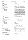
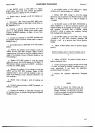
568.
If
an accurate
resistance
decade is
not
available,
adjustment
of the
ohms converter
may
be made
using
resistors
within
l0
%
of Ihe
full-range
value
of I
ke,
100
kf,}
or l0
MO, whose
resistances
are
known
to
within
a
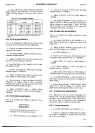
close tolerance"Table
5-10
shows
the
resistance
values
and the
tolerances
required
for valid
adjustment.
The
proper
adjustment
should
be
made
so
that the
3490A
display
reads the
known
value
of the
resistor.
Perfcirm
step
a
of Paragraph
5-67 before
making
a_djust-
ments
in Table
5-10.
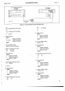
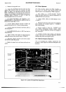
5.69. SAMPLE/HO LD ADJUSTMENTS.
5-70. Adjustment of the
dc
circuits, Paragraphs
5-53
through
560,
must
be
completed
before beginning
the
Sample/Hold
adjustments. The following
adjustments
must be
performed in the
order
given.
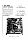
Figure 5-10
shows
the location
of
the
Sample/Hold adjustments. They are
also
shown on the top
guard
cover.
5-71. 0ffset
Gain Adjustment.
5-72. A dc digital
voltmeter
having
a resolution
of
l0pV is
required
for this procedure,
which
adjusts the
gain
of
the
Offset
Amplifier.
c. Adjust A6R32
(l
V HF Adj) for 3490A
display of
1.00000.
d. Change
ac calibrator
frequency
to
100 Hz
and
adjust
A6R27
(1
V LF Adj)
for
display of
1.00000.
e.
Repeat
steps c and
d until
both
readings
are
correct.
5-64.
10 V Range
Ajdustments.
a. Set
34904 RANGE to 10
V.
b.
Set ac
calibrator
output to 10.00000
V
at 100 Hz.
c. Adjust A6R28
(10
V
LF Adj) for
display
of
10.0000.
d.
Change
ac calibrator
frequency
to
100 kHz
and
adjust A6C27
(10
V HF Adj)
for
display of
10.0000. If
maximum limit
of adjustment
is less
than
10.0000,
remove
jumper
wire in series
with A6C28.If
minimum
limit of
adjustment is
greater
than
10.0000,
jumper
wire
probably
has been
removed
and should
be
replaced.
e.
Repeat steps
c
and d until
both readings
are
correct.
5-65.
100
V Range Adjustments.
a. Set 3490A
RANGE to
100
V.
b. Set
ac calibrator
output
to 100.0000
V
at 100 Hz.
,o;.o$|j"rt
A6R3
(100
V
LF
Adj)
for
display
of
tL
d. Change
ac calibrator
frequency
to
100 kHz
and
adjust
A6C6
(100
V HP
Adj) for
display of 100.000.
If
maximum
limit
of adjustment
is
less than
100.000,
remove
jumper
wire in series
with A6C4. If
minimum
limit
of
adjustment is
greater
than
100.000,
jumper
wire
probably
has
been removed
and should
be
replaced.
e.
Repeat
steps c
and
d until
both readings
are
correct.
$66.
O
HMMETER
ADJUSTMENTS.
567.
Adjustment
of the
dc
circuits, Paragraphs
5-53
through
5{0,
must
be completed
before
beginning
this
procedure.
A resistance
decade with
a
correction
factor
chart
(GR
1433-Z)
is
required for the
following proce-
dure.
If
a suitable
resistance
decade
is
not available.
refer
to Paragraph
548.
The
enor
indicated
by
the
correction
factor
chart
should
be
taken
into
account when
adiust-
ins the
ohms
converter.
For
example,
if the
resistanöe of
the
decade
is
high
at I
kQ, the
3490A
display
should
be
adiusted
to
1.00000
plus
the
resistance
decade enor.
_i-16
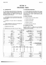
Table 5-10.
Ohmmeter
Adjustment.
3490A
Range
Resistance
3490A
Adlustment
Value
Tolerance
1ko
100 ko
0,000 ks,
900
o
to
1.1 ko
90kato110ka
gMA
to
11 MO
L
O.OO2'yo
t
O.OO25o/o
!
O.O1oÄ
A7R14
A7R16
A7R18