


Section V
AOJUSTMENT
PROCEDURES
Model 3490A
a.
Set
3490A FUNCTION
to
TEST, RANGE to
4.
Set
RATIO switch to EXT REF lV.
Connect short
between
EXT REF Hig[ and Low
terminals.
b. Connect
dc standard to INPUT terminals
and
adjust standard
output
to
+
10.0000 V. If
the display
indicates
Overload, reverse
the
polarity
of the
dc
standard output.
NOTE
Steps
c and d adjust
the zero setting of
the
Extemal Reference Amplifier and
the Feed-
back
Amplifier.
llith the
34904
set to Test
'
4,
the integrator
charges to
the
Extemal
'
Reference
Amplifier
output
and dischmges
to the
!
10.0000 V input.
If the
zero
adjustments
are
set so that the amplifier
output
and
the
3490A
input
voltage are
the
same
polaity,
the
dßplay
indicates Over-
load.
c. Adjust Al3Rl7
(Offset
3) for zero
display. If the
display
goes to
Overload, reverse polarity
of
dc standard
output
and
slowly adjust Al3Rl7
in opposite
direction
for zero
display.
Continue
adjusting
A13Rl7
with
positive
and
negative 10.0000
V
inputs
until
display
reads zero
I
0.0001 V for either polarity
input.
d.
Set
RATIO switch to
EXT
REF I V.
Adjust
A13R8
(Offset
1)
with
positive
and
negative
10.0000V
inputs
for display
of zero t
0.0001
V.
e. Repeat steps c
and
d
until
display is zero
t
0.0001
V for both positive
and
negative
inputs
on
both I V
and
10 V EXT
REF
ranges.
f. Remove
short
and
connect I Mf2
resistor to EXT
REF
terminals.
a. With 3490A
set to l0 VDC
RANGE, TRACK/
HOLD,
SAMPLE
RATE fully
clockwise,
and
dc
standard
connected
to input
as
in previous
adjustment,
set
dc
standard output
to
+
10.0000 V.
b.
Adjust
A27R6, DA
Gain, for display of
+
10.0000
V.
(Display
will be
noisy.)
S77.
Response
Adjustment.
5-78. This
procedure
requires
a function generator
(-hp-
3310A), a
silicon
drode,
a l0kQ
resistor and an
oscilloscope
having a delayed
sweep
and
a delayed
gate
output
(-hp
l80C/DllOSlAllS2lA).
The
delayed
gate
output
must be a
negative-going pulse
with
an
amplitude
of 2
to
200
V and a width of at least
30
nanoseconds.
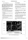
a. Connect
equipment
as
shown in
Figure 5-7.
If the
3490A has BCDiRemote Expand
Option
020, also
connect Stretched
Pulse
Output
(J7
pin l0) to External
Encode
(J7
pin
28).
b.
With 3490A set to l0
VDC RANGE
and TRACK/
HOLD as
in previous
adjustment, set
SAMPLE
RATE to
HOLD.
c.
Set
oscilloscope
controls for External Trigger,
negative slope
and
Main
sweep.
Set
Main sweep to
.1 ms/div., Delayed sweep to I
ps/div.
d. Set
function
generator
to square
wave, frequency
to I kHz,
and adjust output level
for
20
V
peak-to-peak
signal
as displayed on oscilloscope.
e.
Adjust
oscilloscope
delay control
so that
intensi-
fied
trace
begins approximately 450
gs
after
negativg-
going
transition of square
wave. Note 3490A readin$,
which should
be
near
zero.
f. Adjust
delay
so
that
intensified
trace
begins
approximately
120
ps
after negative-going
edge of square
wave.
C.
Adjust
A27R3, Response,
for display noted in
step
e.
h. Remove
top guard
cover
and move
"5th
Dgit
Blank"
wire
from Test Point
M to Test Point
L.
i.
Replace
and
secure
top
guard
cover.
5.79. RATIO
REFERENCE
ADJUSTMENTS.
5{0. Adjustment
of the
dc
circuits, Paragraphs
5-53
through
5{0.
must
be
completed
before beginning
the
Ratio Reference
Adjustments.
A dc standard
(-hp-
74OB), a I
M t
l0%
resistor
(hp-
0698-1051) and a
stable
voltage
source
between
9.5
V
and
10.5
V, such as
a mercun'
battery (Mallory
TRl77),
are required for
these
adjustments.
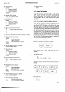
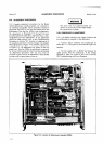
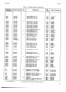
Figure
5-1 I
shows the location
of
the
Ratio
adjustments.
They
are
also shown
on the top
zuard
cover.
}l5
Or;rra
-l
H I
) lcÄeiel
/t11 |
L:t-Jg
.E
ot3
[i----l
I
u5
|
tr
7l
öEEEEilEE
t
X9**t
i**++QoL
g,lqe
I I
|
-Rr8-
TTfn0000000000
At3
hp Porl
No.03490-66513
Figure
5-1
1.
Location of Ratio Adjustments.