


Model
34904
Section
IV
SECTION
IV
THEORY
OF
OPERATION
4I.
INTBODUCTION.
42.
This
section
describes the
methods
and
circuits
used
in
the
Model
3490A
Multimeter to
make
dc
voltage,
ac
voltage,
and resistance
measurements.
The
circuits
needed
for ratio measurement,
sample-and-hold
measurements,
remote
control,
and
data
output
are also
described.
A
general theory
ofoperation
is
followed
by a
more detailed
explanation of the circuits
used.
+3.
GENERAL
THEORY
OF
OPERATION.
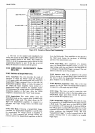
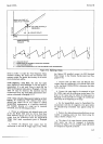
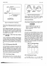
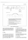
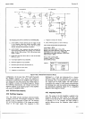
44.
The Model
34904
Multimeter
uses the
dual-slope
integration technique for
measurement
(see
Figure
4-1),
in
which
an integrator charges
for
a fixed length
of
time
to
a voltage
proportional
to the
input sigral,
and then is
discharged
at a fixed
rate
determined
by a known
reference
voltage.
The
measurement
display is
deter-
mined by
the
discharge time,
which
is
proportional
to
the
input
sigral.
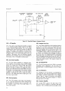
The
integrator is part
of
the
Analog-to-
Digital Converter shown
in
the Basic
Block
Dagram in
Figare
4-2.
A
description
of
the
basic operation
of
the
3490A
is
contained
in Figure
4-2
and
Paragraphs
4-5
through
4-l 8.
45.
Signal
Conditioning
Gircuits.
46.
The signal
conditioning
circuits include
the
DC
Input Attenuator,
the
AC
Converter,
and
the
Ohms
Converter
circuits.
The
output
ofone
ofthese
circuits is
applied
to the
DC
Amplifier
for
the run-up portion
of
the
measurement
sequence.
47. Reference
Voltages.
4-8.
One of
three
reference
voltages
is applied to
the
DC
Amplifier
input
for
the
run-down portion
of
the
measurement
sequence.
The
proper
reference
is selected
by the
Logic circuits
according
to the
function
selected
and/or the polarity
of the input
signal.
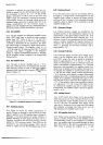
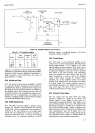
+9. DC Amplifier.
z1-10.
The
DC
Amplifier
output is l0
Vdc
for
a full-
range input
on
any range in
any function.
For
any
measurement
except
Sample/Hold, this
output goes
to
the Analog-to-Digital
Converter circuits.
In
Sample/Hold
measurements,
the DC
Amplifier
output is
applied to the
Sample/Hold
circuits
(see
Figure
421),
nd the
Sample/
Hold
output
is
applied to the
A-to-D
Converter.
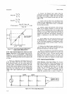
4l 1. Analogto-Digital
Converter.
412. The
Analog-to-Digital (A-to-D)
conversion
circuits
consist
of
an
Integrator,
followed
by a x20 Amplifier
and,
a
Zero
Detect Amplifier.
If the Integrator
input
is
positive
during
run-up,
the
A-to-D output goes
HIGH
(near +
5
V)
during run-up
and retums to
LOW
(near
0
V) when
the
Integrator
is
discharged to
zero. If
the
input
is negative,
the
A-to-D
output
goes
LOW during
run-up
and
HIGH
at the zero
detect
point.
Input
signal
polarity,
as well
as
"end
of
measurement"
information,
is
derived
from this
output
signal. The
length
of time
between
the
start
ofrun-down
and
the zero
detect
point
determines
the numerical
value
of the
display.
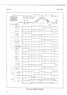
413.
Logic.
4-14. The
timing
of
the
measurement
sequence
is
.
.qontrolled
by
the logic
circuits.
This timing
may
be
influencöd
by the
range
and function
selected.
The
basic
'"'
clock
is
a crystal-controlled
oscillator,
from
which
a
number
of timing
signals
are derived
through
dividing
counters.
The
sample
rate is
controlled
by the
logic
GREATER
INPUT
_
SMALLER INPUT
-
- -
- -
.r\?
ßüy
\-
RO
INTEGRATOR
CHARGES
FOR
FIXED TIME.
INT€GRATOR
DISCHARGES
AT FIXED
RATE.
3490-8-3584
Figure 4-1.
Dual-Slope lntegration.
4-1