


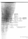
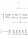
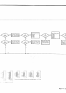
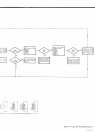
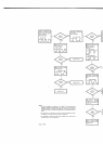
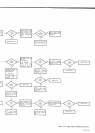
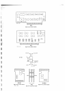

Connect oscillosope
to
AlTPU and monitor State
Clock output. Set scope
to
Inr. Sync
+Slope.
Correct
waveform:
SEE
NOTE
t.
Monitor
11 ol AlUl2.
SE€
NOTE 1.
Monitor
pins
and 7 of A1
U2.
l+5nsl
:;[-r
t'!
.o."
1-
_,;ljl-
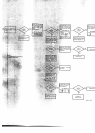
Monitor
pin
11
ol
A1U4.
Monitor
pin
14 oI A'lUs
Correct waveform:
E
NOTE 1.
Monitor
pin
1U4. Both
pins
should
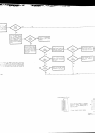
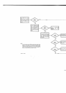
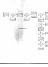
Refer
to Loqic
Trouble-
shooting
suggestions
in Par-
agraph
7-39.
M(
Sct
po
+i
YES
YES
YES
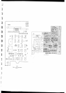
NOTES:
1.
To monitor waveform or
voltage, first turn 34904 OFF, then while
holding
MANUAL
TRIGGER button
detressed,
turn
instrument ON and m@sure the
necesgry waveform
or
voltage.
The
pushbutton
must
be
held
in while the
measurement
is bken-
This
procedure
applies oßly to those tests which
refer to
Note
1
.
2. The time shown
on waveforms is
correct
for
instruments designed lor
60
Hz
line operation.
For 50 Hz instruments,
increase time by 20%.
3- An oscilloscope
is
required {or these checks. Voltages
ruv
be
m@sured
with
sufJicient
accuracv
wiih
an
oscilloscope.
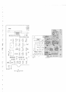
34904- 0
-
2$7