


Section
IV
that
the
data
has been accepted,
the
Outguard ASM
signals
to the
Inguard ASM
that new
data
may
be
transferred
across
guard. The output
of the six
digits of
measurement
magnitude
is
timed
by
the
same
scan
signals
(HSA,
HSB, HSC)
that
control
the
3490A
display.
4-211.
Talk Only.
When
the
rear
panel
slide switch
is
set
to the TALK ONU/
position,
the 34904
may
be
operated with
a
printer
without the
use
of
a
controller.
This
switch sets
the
internal Talk
Only
line
LOW,
enabling
the
I/O
circuits to
output
data
after each
measurement. Operation
of the
3490A is programmed
by
the front
panel
controls.
+212.
SAMPLE/H0tD 0PTl0N ll40
or
045.
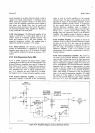
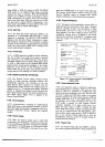
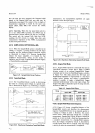
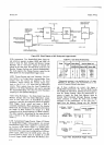
4-213.
When the
SampleiHold
option is
installed in the
3490^, it
occupies
a
position
between
the DC Input
Amplifier and the
Analog-to-Digital
conversion
circuits
as illustrated in Figure
4-21 . Because
Sample/Hold
follows
the Input
Amplifier, it
is
limited
by
that
amplifier's
characteristics.
Either
of two modes
of
operation may
be used; Acquire/Hold
(delayed
trigger),
or Track/Hold
(non-delayed).
Figure 4-21.
Sample/Hold
Circuit Position.
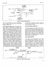
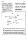
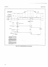
4-214. Twk/Hold
Mode.
__-"
4-215. The
Track/Hold
Mode is
useful in
determining
the
value
of
a varying input
voltage
at a specific
time.
This
is illustrated
in
Figure 4-22.Following
a complete
FiEure 4-22.
Waveforms
lllustrating
Track/Hold
Mode.
1-ll
Model3490A
measurement, the
Sample/Hold amplifiers
are
again
allowed to track the
input
signal.
HoLo MooE
--._J
MEASUREMEN,
pERroD
_Jf
EXTERNAL
SAMPLE/HOLD
TRIGG
ER
34904 B'3411
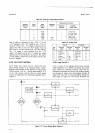
Figwe
4-23. Waveforms
lllustrating
Acquire/Hold
Mode.
4-216.
Acquire/Hold
Mode.
4-217. Acquire/Hold
operation is essentially
the same
as
Track/Hold
operation, except that
a delay
is
added
between
receipt of
an
external
Sample/Hold Trigger
command
and
the time the
Hold Mode
begins, as shown
in Figure
4-23. This
delay
permits
the DC Input
and
Sample/Hold amplifiers
to
respond
fully
to
a
step input
voltage before holding
and
taking
a measurement,
making it
possible
to
apply
a Sample/Hold Trigger
command simultaneously
with a
step input
voltage.
The
lengih
of
the
delay
is
dependent upon the
range selected,
as shown
inTable 44.
Table
44. Acquire/Hold Delay.
Range
Delav
Option 050
Option
060
1V
10v
100 v
1000 v
615.0rts1400ns
154.0
ps
t
400
ns
615.0
rrs
t
400 ns
154.0
ps
t
400
ns
512.6
ps
t
400
ns
128.4
tts
t
4p0
ns
512.6
trs
i
zl00
ns
128,4
tts
+
400
ns
4-21
8.
Sample/Hold
Mea$rement
Sequence.
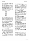
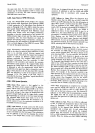
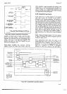
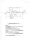
4-219. Figure 4-31 shows
a
simplified
diagram of the
Sample/Hold
circuits
and
describes
the
measurement
sequence.
Sample/Hold Circuit A can
respond
quickly to
a change
in voltage
at point
2. However,
this circuit
cannot
hold a
fixed level
long
enough
for
a complete
measurement.
Sample/Hold
Circuit B cannot
respond as
quickly
as
A,
but
can
hold
a fixed level
long
enough for
a complete
measurement.
In
a
Sample/Hold measure-
ment, the
voltage
is
sampled
by Circuit
A,
then
held by
A
until
Circuit
B has time
to
respond. Then
the voltage
is
held by B while
the
measurement
is completed.
ANALOG
TO
DIGITAL
CONVER
SION
CIRCUITS
VOLTAGE
LEVEL MEASURED
AT THIS
TIME
+TRACK
MOoE
O MODE EEGINS WITHIN
NANOSECONOS
AFTER
ElPT OF
THE
S/H
TRIGGER
MEA5gREMENT
pERroD-
-/
iX]ER^iAL
SAMPLE/HOLD
TRIGGER
1490a'B
3430