


Section IV
50 Hz instruments.
Two
Sample/Hold
State Clock sig-
nals which
are
opposite in phase,
HSHC
and
LSHC,
are
used to
clock
the
State
Storage
and Memory
Storage
flip-flops.
All
six
"next-state"
signals
are clocked
into
storage
at
the
same time.
One-half
clock
cycle
later, the
Memory
Storage
flip-flops
are
clocked
simultaneously.
The
clock signal
to
the
Timing
Counter is
gated
by the
Hold sigral
from
the
Sample/Hold
Trigger
circuit.
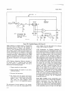
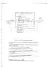
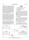
4-232. Timing
Counter
and Level
Translator.
The Tim-
ing
Counter is
a
l4-stage
binary
counter/divider.
Four
outputs from
this
counter
are
applied
to the
kvel
Translator,
which
converts
the
counter
output
logic
levels
to the
0 V to
+
5
V levels
used
by subsequent
circuits.
Three
outputs
from
the
trvel
Translator
arg.
applied
to the
Delay
Multiplexer
and
used in selecting
the Acquire/Hold
delay. The
other two
kvel Translator
outputs go
to
the
Qualifier
Multiplexer.
4-233.
Delay
Multiplexer.
Two
Delay
Select
lines
from
Memory
Storage
select
the
Delay
Multiplexer
output
from
its
four
input
lines.
If
Track/Hold (no
delay)
operation
is
selected,
the
multiplexer
selects
the
Sample/
Hold
Trigger
Circuit output
and issues
a Hold
A
command
immediately.
When
operating
in the
Acquire/
Hold
mode,
the
multiplexer
output
(Hold
A) determines
the
length
of
delay
between
the
receipt
of
a Hold
command
and the
actual
beginning
of
a Hold condition.
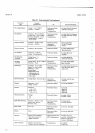
The
delay
required
is
determined
by
the
range selected,
and is
related
to
the
DC Amplifier
gain,
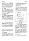
as shown
in
Table
4-5.
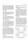
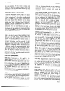
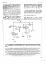
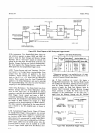
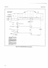
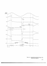
4-23.
Sample/Hold
Trigger
Circuits.
Figure
4-29
shows
the
Sample/Hold
Trigger
timing
sequence.
An external
Sample/Hold
Trigger
pulse
is
applied to
a
pulse-stretch-
ing
one-shot
circuit
whose
output
is
a
positive
pulse
approx-rmately
40
microsqconds
in
width, called
Exter-
nal
Hold
H.
This
output
may
be inhibited
by
a
LOW
true
inhibit
sigral.
LISH,
from
the
ASCII
option. Also,
the
Ertemal
Hold
H
output
must
be enabled
by a LOW
Ertemal
Triaeer
Enable
signal
from
the Mem'ory
Stor-
l-'h
Model3490A
*
Measurement
accuracy is not
specified
for
the
.1 V
range.
Operation on this
range is not recommended
due to
the
amount of
Gaussian
(thermal)
noise
present.
age. If these conditions
are correct, this
begins a
Sample/Hold measurement.
The
External
Hold
H
pulse.
also
enables the Clock
Gate, allowing
the
Clock signal
to
start
the Timing
Counter.
After
the
measurement
se-
quence
is
begun, the
Read Only
Memory
issues
an
Internal
Hold Command
(through
Memory
Storage)
which continues
to
enable the
Clock Gate for the
remainder
of the measurement. At the
same time,
a
sigral
from
the Memory
Storage
sets the
External
STATE
CLOCK
HSHC
DELAY
SELECT
LINES
IHOSA,
HDSEI
FROM
MEMORY STORAGE
SAMPL€/HOLD TRIGGER
IHEHCI
FROM
llrsHt
FRoM
ascrl
EXTEfrNAL
TO
OUALIFIER
MULTIPLEXER
1490-8-3440
EXTERNAL
TBIGGER
ENASLE
(LXEN}
FROM
MEMORY
STORAGE
LSHC
INVERTED
TO
OUALIFIEF
STATE
CLOCK
MULTIPLEXER
Figure
4-28. Block
Diagram
of
S/H
Timing
and
Trigger Circuits.
Table
4-5.
Gain Delay Relationship.
Range
DC
Amp
Gain
Delay
Select Nominal Delay
(psl
HDSEHDSA
Option 060
Option
05t0
,1
V.
1V
10v
100 v
1000 v
xlOO
xlO
xl
xlO
xl
L
H
L
H
L
L
L
H
L
H
2048.8
512.6
128.4
512.6
124.4
2458.5
615.0
154"0
615.0
154.O
EXTERNAL
TRIGGER,
ENABLE LXEN
EXTERNAL
;s,t3i5'/rp,ly,ffi
EXTERML HOLD H
HEHS
I NTERNAL
COMMAND
H
IHC
HOLD
H
TRIGGER COMMANDS
INHIBITED
l3O
rs--J
Figure
4-29. Sample/Hold
Trigger Timing.