


Section
V
$51.
ADJUSTMENT PROCEOURES.
5-52.
Complete
adjustment
procedures
for the Model
3490A
Multimeter,
including
options,
are contained in
the
following
paragraphs.
These
procedures
should
be
performed
only
after
it has been determined
from
the
Performance Tests
that
the 3490A is
out of
adjustment.
The adjustments
in
Paragaphs 5-53 through
5-60 must
be
performed in
the order
given,
and before the
ac, ohm,
sample/hold
and ratio
adjustments. If
any adjustment
cannot be
made
correctly, refer to the
Troubleshooting
Procedures
in
Section
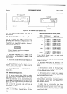
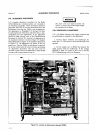
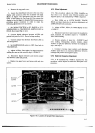
VII. Location
of adjustments in
the
standard
instrument
is shown
in
Figure
5-9, Sample/
Hold adjustments
in Figure 5-10,
and Ratio
adjustments
in Figure 5-l
l. All
adjustments are shown
on
the
top
guard
cover.
Turn the
3490A
on and
allow it to
warm up
for at
least 4 hours with the covers on
before
performing
the
adjustment
procedures.
The top
cover must
be
removed
to
gain
access
to the
adjustments,
which should
be
made with
the
guard (inner)
cover
on.
ADJUSTMENT
PROCEDURES
Model
3490A
wARiltr{G
The inner
cover
is
qt
Guard
potential.
Use
caution
to
prevent
shock when high voltages
are connected
to the
Input.
5.53.
POWEB
SUPPLY
ADJUSTMENT.
5-54.
A dc digital voltmeter with
4digit
resolution
and
an oscilloscope are
required
for this
adjustment.
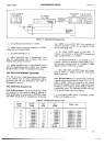
a. Connect digital
voltmeter and
oscilloscope
be-
tween the
+
17
V test
point
on AlAl and the input
Low
terminal.
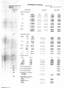
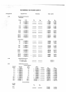
c.
Set
the sample rate on
HOLD
and measure
the
ripple present
with the oscilloscope.
If the
voltages
specified in Table 5-9 cannot be met, refer to
Section
VII, Troubleshooting
and
Circuit
Diagrams.
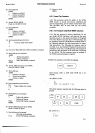
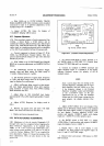
f,:
Al
F429
THERMALADJ.
w
46R28
i
lOV
LF
ADJ
J
fi=i"l;
A7R16
i
1OOK ADJ
Figure
5-9. Location
of
Adjustments,
Standard
3490A.
i !!