


Section
II
2.16.
INSTALLATION.
2-17. Bench Use.
2-18.
The Model
3490A
is shipped
with
plastic
feet and
tilt stand
in place, ready for use
as a bench instrument.
The
front of
the instrument
may
be
elevated
for
convenience
of operating
and viewing
by
lowering the
tilt
stand. The
plastic
feet
are shaped
to permit placing
the
instrument
on top
of other full-module
Hewlett-
Packard
instruments.
2-19. Rack
Mounting.
2-20.
The Model
3490A
may
be rack
mounted using the
rack mount kit
(-hp-
0349G84401)
supplied
with
the
instrument.
Instructions
are
included
with the kit. The
rack mount is an
EIA
standard
width
of
19
inches. When
mounted
using the
rack mount
kit, additional support
must
be
provided
at the
rear of the
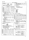
instrument. The
dimensions of the Model 3490A
are shown
in Fizure
2-3.
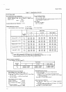
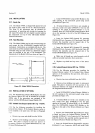
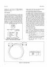
Figure
2-3. Model 3490A
Dimensions.
2.21. INSTALLATION
OF OPTIONS.
2-22.
T}te Isolated
Data
Output
(BCD)
Option
021
and
the Remote
Option 022
may be installed
in
the
Model
349OA
only if
the instrument
was
equipped
at the
factory with
the BCD/Remote
Expand
Option 020.
2-23.
lsolated
Data
0utput
0ption 021
(-hp-
111ZlAl.
l-24.
Use the
following
procedure
for installing
the
Isoiated
Data
Output. If
the Isolated
Remote
option is
to
be installed
at the
same time,
refer
also to Paragraph
a. Remove
top
cover
and shield from the
3490^.
b.
Remove
screws
holding cover plate
to instrument
s:rard.
This plate
is located
in left
rear
portion
of
rnsrrument
between
the Inguard
Motherboard
Al and
Out suard
llotherboard
A8.
Model 3490A
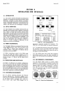
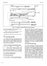
c. Install 03490-60306 Isolated
BCD
Module in
the
right opening
in
the instrument
guard
using screws
provided (see
Figure 2-4).
d.
If
Isolated Remote
(lll22L)
is not installed
at
this
time, install cover plate
03490-04117
over the left
opening
in the guard.
If Isolated
Remote is
to
be
installed,
place
the 03490-60308
Isolated
Remote
Mod-
ule in the opening to
the left of the
BCD
Module
(see
Figure
24).
e. Insert the Isolated
BCD Inguard
PC
Assembly
0349U66509 into
Connector AlJ8
and install
Cable W4
between this Assembly
and the inguard
side
of the
Isolated BCD
Module
(see
Figure
24).
f. Insert the Isolated
BCD
Outguard
PC
Assembly
03490-66510
into Connector A8J9
and
install
Cable
W5
between this
Assembly
and
the
outguard side
of the
Isolated BCD
Module
(see
Figure 2-4).
g.
Make sure all
boards are
seated properly
and
all
cables
are securely inserted
in their connectors.
h. Replace
top
shield
and top cover
of the instru-
ment.
2-25. f
solated
Bemote 0ption 022
(-hp-
11122A1.
2-26.
Use the following procedure
for
installing
the
Isolated
Remote option. If the Isolated
Data
Output
option is to be installed
at the same time,
refer
also to
Parugraph2-23.
b.- Remove screws
holding cover plate to instrument
guard.
This plate is located
in left
rear
portion
of the
instrument between the Inguard
Motherboard
Al and
the
Outguard Motherboard
A8.
c.
Install
03490-60308
Isolated
Remote Module in
the
left opening in the
instrument guard
using screws
provided
(see
Figure
2-4).
d. If Isolated BCD
(11121A)
is not installed
at
this
time, install
cover
plate
03490{4117
over the
right
opening in the
guard.
If
isolated BCD
is to
be
installed,
place
the
03490-60306 Isolated
BCD
Module in the
opening
to the
right of the Remote
Module
(see
Figure
24).
e.
Remove the
03490-66504
Inguard
Remote Jump-
er
Board ard
insert the
Isolated
Remote Inguard PC
Assembly
0349U66511 into
Connector AlJT
and
install
Cable
W6
between
this
assembly
and
the inguard
side of
the Isolated
Remote Module
(see
Figure
2-4).
f.
Insert
the Isolated
Remote Outguard PC
Assembly
0349046512
into
Connector A8J10 and install
Cable
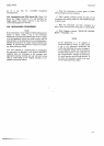
OIMENSIONS
IX INCHES
ANO
MILLIMETERS
I
(9r.4)
T_