


Model3490A
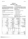
a.
Remove
the
toP
guard cover.
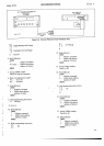
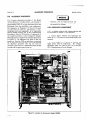
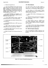
b. Locate
the white/black
wire
just
to the rear
of the
display
cable
connector.
This
wire
is labeled
"5th
Digit
Blank" in
Figure
5-10.
Disconnect
this
wire from
Test
Point
L and
connect
to Test
Point M. This
restores the
display
to five
full
digits
for
Sample/Hold
measurements,
providing
greater
resolution
in
order
to
make the
following adjustments
more accurately.
c.
Set
3490A
FTINCTION
to
DC, RANGE
to IO
V.
SAMPLE/HOLD
to TRACK/HOLD, SAMPLE RATE to
HOLD.
Short
input
Higfr
to
Low.
d.
Connect
digital
voltmeter between A27TP3
and
ground
test
point on AlAl.
Record
voltage reading.
e. Connect
jumper
wire between
Test
Point
LTST
on
A28
and
ground.
f. Set
SAMPLE/HOLD
switch
to
OFF.
then
back to
TRACK/HOLD.
g.
Adjust
A27Rl4,
Gain Adjust,
for digital
voltmeter
reading
the same as that
noted in step
d
I
0.0005 V.
h. Dsconnect digital voltmeter
and remove
jumper
wire between
LTST and
ground.
i.
Replace top
guard
cover
and secure
with only two
screws.
ADJUSTMENT
PROCEDURES
Section
V
5-73. 0ffset
Adjustment.
5-74.
This
procedure
adjusts
the
Offset Amplifier
so
that
there is
no turnover
error
between positive
and
negative
inputs.
A dc standard
(-hp
7a0B) is required.
a. With 3490A
set
to IOVDC
RANGE,
TRACK/
HOLD,
and input
shorted
as in
previous
adjustment,
set
SAMPLE
RATE
fully clockwise.
b. Adjust
A27Rl3,
Offset, for
3490A
display
of zero
t
0.0001
v.
c.
Dsconnect input
short
and connect
dc standard
to
input terminals.
Set standard
output to
+
10.0000
V.
Note 3490A
reading.
d. Reverse
polarity
of input
(to
-
10.0000
V) and
note
reading-
Disregarding
polarity
display, adjust
A27Rl3
to split
the
difference
between the
readings in
step
c
and step
d.
I
i'
e.
Continue
reversing
input
polarity
and adjusting
A27Rl3
until
there
is no
numerical
difference
between
readings
with
positive
and
negative
inputs.
$75. Dielectric
Absorption
Adjustment.
5:76.
A
dc
standard (hp-
7a0B) is
required for
this
procedure,
which adjusts
the
dielectric
absorption
com-
pensation.
sth
DtGtT
BLANK
A27TP3
A27R14
A27R13
Figure
5-10.
Location
of
Sample/Hold
Adlustments.
5-17