


Section
III
3-96.
DAV.
After
the talker
places
data on the
data
lines,
it
must set DAV LOW to indicate
that
the data
is
vatid.
A
listener
may
not
process
data
until DAV
goes
LOW.
DAV cannot
be
set HIGItr
again until
DAC
goes
HIGH,
indicating that all
listeners
have finished proces-
sing
the
data.
3-97.
DAC.
When
all
listeners
have
accepted
data, DAC
goes
HIGH, indicating to the talker
that
the
data is no
longer
needed. A listener
may set
RFD to
HIGH
at
the
same
time
or at any
time
after
DAC
goes
LOW, to
indicate
that it is
ready for new
data.
3-98.
Service
Request,
LSRO. Any
unit
on the
bus
having service
request
capability
may set
SRQ LOW at
any time. This
indicates
that
a unit
wants
the
attention
of
the controller.
The
controller
may then
check each
unit
on the
bus individually
to
see
which
unit or units
pulled
SRQ LOW, or it
may ignore
the service
request.
LSRQ
does not
hinder
other normal
operations
on the
bus.
3-99. End
Output, LEOP. When
the
controller
sets
the
End
Output line
LOW, all units
immediately
stop
driving
DIOI
-
8, MRE,
DAV,
RFD,
and
DAC. When
EOp is
HIGH,
all
units
may operate
according
to the
normal
bus
rules.
3-100.
Remote
Enable,
REN. All
instruments
on the
bus
are enabled
to
respond to
remote
programming
data
if
the
controller
holds the
REN
line
LOW.
The
3490A
may
be set to
remote
operation
by setting
REN
LOW
and
sending
its
listen
address.
It
may
be returned
to
local
(front
panel)
control
by
setting
REN
HIGH.
An excep-
tion
is
noted
in Paragraph
3-107.
Normally,
all units
on
the
bus
respond
to
their
front panel
controls
when
REN
is HIGH.
3-101. Talk
0nly
(No
Controller).
3-102.
The
3490A
with
the
GPIB option
may
be
used
to provide
data to
a
printer
without
having
a controller
on the
bus.
The printer
must be able to
accept
the ASCII
data
information
and
to handshake
with the
3490A
on
the
RFD,
DAV,
and DAC
lines.
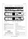
The slide
switch
on the
3490^
rear panel
must
be set to
the TALK
ONLY
position
(see
Figure
3-1).
The instrument
is
then
controlled
by
the
front
panel
controls
for
selection
of
function,
range,
Sample/Hold,
and
trigger
mode.
The
349OA
may
be
triggered
through
the
rear panel
Trigger
Connector
Jll,
or
allowed
to sample
at a rate selected
by
the
SAMPLE
RATE
control.
When
a
controller is
connected
to
the
bus,
the
rear
panel
switch
must
be
set
to the ADDRESSABLE
position.
3-103.
GPIB
Control
of
3490A.
3104.
Listen
and
Talk
Addresses. The
34904
may
be
addressed
to
listen
or
to talk
by setting
MRE
LOW and
sendine
the
proper
listen
or talk
address. Each
34904
GPIB I
O
is
normally
programmed
at the
factory
for
a
_r,ö
Model3490A
listen
address
of
6 and
a
talk
address of V.
If two
or
more
instruments
are
to
be operated on the
same
bus,
they
should
not
have the same
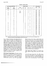
address. Table 3-6
lists
the
address
codes
possible.
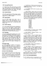
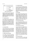
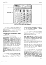
Address is
selected
by
positioning
jumper
wires in
a header on the
Outgrrald
Mother Board
Assembly
A3
1, shown in
Figure
3-7.
Remove
the top
cover
to
gain
access
to this
header.
Note
that
only
five
binary bits of the
7-bit
format
are
selectable.
These
five
bits are the same for
both
the
listen
and
talk addresses.
The
sixth
and
seventh
bits
are
provided
by the
controller
to
determine whether
the
address
is
a
talk
or listen address;01
for listen.
l0
for
talk.
Absence
of a
jumper
is a logical
"1";presence
of a
jumper
is
a logical
"0".
At least
one
jumper
must
always
be
installed,
because
the 11 1
I 1 address is
not
allowed.
This code
is used to
unaddress the instrument
to talk
or
listen.
.-al
--] |
R6
lr
I u4 I -^
a3ll
rÄi+: -cg-
lL
-
Rlz- aeli
l^^. |
-
Rrs-
--
li
F-
I
F<
J>
Figure
3-7.
Position
of
Jumper Wires
on Outguard
Mother
Board
Assembly A31.
3-105.
Addressed
to
Listen.
When the 3490A
is
first
turned
on,
the
GPIB
programming
circuits
will conform
to
the front panel
control settings. It
must
be
placed
in
remote control
before
programming.
3-106. Remote Control. To place
the 3490A in
remote
control, set
MRE
and REN to
LOW
and transmit
the
3490A
listen code.
REN
must be held LOW continu-
ously
to maintain
remote control. When the
instrument
is first
set to
remote control, the
GPIB circuits store
the
front
panel
range and function
selections.
Sample/Hold
mode
is
Off
(S0),
Trigger is set to Internal
Sample Rate
(TQ),
and Mode
of Operation is Addressed
Multiple
with
No
Output
(M0).
AnV chalges in this
programming
must
then
be
made by remote
control. LMRE
must
be
set
HIGH and the
remote
programming
data transmitted.
The
3490A
will accept only the
alpha
identifiers
E,
F,
M, R, S and T,
and digits 0 through
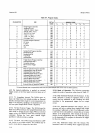
7. Table 3-7
lists the
3490A program codes.
The 3490A may
be
unaddressed
to
listen by sending
the
character
?.
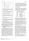
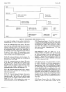
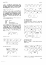
Figure
3-8 is
a
timing
diagram for
data and
handshake lines
when the
3490A
is addressed
to listen.
3-107. Return to Local
Control. The 3490A
may
be
returned to local control
by
setting
REN
HIGH.
How-