


Section III
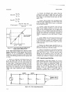
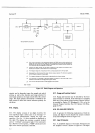
vs-ve
Slope AB
=
-
Ts-Ta
Vc
-vs
Slope
BC
=
-
Tc-Ts
Slope
BC
-
Slope
AB
%
Non-Linearity
=
x
100
Slope
AB
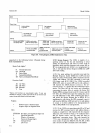
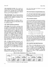
Figure
3-13.
Using
Delayed-Sweep
Oscilloscope
in
RamP
LinearitY
Measurements.
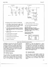
&178. Filter
Response Measurement
Aided by
an Oscil-
loscope.
Measurement
of filter
response may be accom-
plished
by the
use of Sample/Hold,
a
delayed-sweep
oscilloscope,
a square
wave
generator,
and
a
time interv-al
counter.
The
following procedure
tests the
response
tiniö
ofa
filter.
a.
Choose
an oscilloscope with
delayed
sweep,
such
as the
-hp-
Model l80C
with
the 1821A
Time
Base/
Delay
Generator plug-in
unit. The
vertical
plug-in
may
be either
single- or
dual-channel. However, the
dual-
channel
feature permits
display of both the
filter
input
and
output
at the
same time. Be
sure
the
Delayed
Gate
output
from the
oscilloscope meets the
Sample/Hold
Trigger
input
signal
requirements
given
in Paragraph
3-1
60.
Model3490A
b. Connect
the
Delayed Gate output from the
oscilloscope to
the
S/H AC Trigger
input. If
the 3490A
has
Option
020 installed, connect the
S/H Stretched
Pulse
Output
to the Extemal Encode
input
(see
Para-
graph
3-170).
c. Connect both the Main
Gate and
Delayed
Gate
outputs from the oscilloscope
to an
interval timer,
such
as
the
-hp-
Model
5300A15302A
Counter,
to
determine
the time delay accurately.
d. Connect
a
square wave
generator,
such
as
the
-hp-
Model 33llA Function
Generator,
to
both the
filter
input and
the
oscilloscope input.
Set
the square
wave
output to l0 V at
a frequency such that the
duration of
one half of the square wave is
greater
than the expected
response
time
of
the
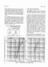
filter. For
example, a frequency
of
300
Hz
is satisfactory
for the filter shown in Figure
3-14.
e.
Set the
3490A
to the
l0
V range, DC function
and
Track/Hold operation.
Connect
the
output of
the
filter
to
the
3490A
input
terminals.
If
a dual-channel oscillo-
scope is used, also connect the hlter output to the
other
oscilloscope input.
f. Position the
delayed sweep intensified trace
to-
ward the right side of one
half of
the square
wave
and
determine
the
final value of
the filter output.
g.
Shift
the intensified
trace toward the left
until the
3490A reading
is
reduced
to within XVo or X mV of the
final value
noted
in
step f.
The time interval counter
displays
the time required to settle
to this
value. The
intensified
trace may be
positioned
at
the
other
points
to observe
any
overshoot
or ringing
in the
filter oütput.
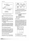
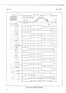
3-179.
Using the Acquire/Hold Mode.
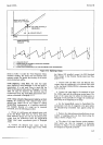
3-180. Measuring a
Step
Input
Voltage.
The
Acquire/
Hold
mode of operation
is
useful for measuring
a
step
input voltage because
the
Sample/Hold Trigger
com-
mand
may be applied
simultaneously
with the input
voltage step. The aperture time,
which
is
the
delay
between
receipt
of
a
Sample/Hold
Trigger
and the
beginning of a Hold mode, is of sufficient length
to
include
the acquisition
time,
as
shown
in Figure
3-l 5.
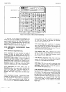
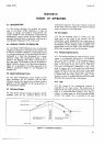
5o6mH
3490A
W|TH
SAMPLE
/HOLD
5e6
mH
,"1
",1
A
A
DELAYED SWEEP
GATE OUTPUT
_1-10
Figure
3-14. Filter
Output
Measurement.