


Section V
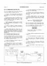
5.22.
AC
COMMON.MODE
REJECTION
TEST.
5-23.
An
ac
calibrator
(hp-
7a5A)
and
an
electronic
counter (-hp-
53004) are required for this
test.
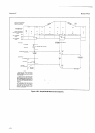
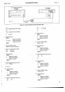
a. Connect a
I kCl resistor
between
input
High
and
Iow
terminals, and
connect
High to
Guard
as sfiown in
Figure
5-3.
b. Connect electronic counter
to
ac
calibrator
output
and adjust calibrator frequency
to
60 Hz
t
O.l
%
if the
349OA is
desigred for
60 Hz
line
operation,
50
Hz
!
0.1
%
if
it is a 50
Hz model.
c. Before connecting
ac calibrator
output to
3490A,
set
3490A FLJNCTION
to DC.
RANGE to
I
V. Note
3490A
reading.
d. Connect ac calibrator
to
3490A
as
indicated
in
Figure
5-3
and set output
voltage
to
70.7 Vrms
(100
V
peak).
e.
3490A
reading should
not
change
more than
0.00001
V from
the reading
noted in step
c,
verifying
ac
common-mode
rejection
of 2140
dB at the
frequency
specified
(50
Hz
or 60 Hz),
using the
formula
given
in
Paragraph
5-21.
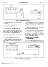
S24.
AC
NORMAL.MODE
REJECTION
TEST.
5-25.
AC normal-mode
rejection is
the
ratio of
the peak
normal-mode
voltage
to the
resultant error
in
reading.
An ac calibrator
(-hp-
7454)
and an electronic
Counter
(-hp-
5300A)
are required
for this
test.
,-..
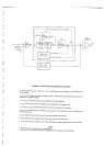
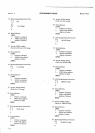
a. Connect
test
equipment
as shown in
Figure
5-4.
Do not
connect
to
3490A input.
i^
b- Using
an
electronic counter
as
a monitor,
adjust ac
calibrator
frequency
for
60 Hz
t
0.1
%
if
3490A
is
designed
for 60
Hz line
operation,
or 50.H2
!
O.1
%if
it
is a 50
Hz model.
Model
3490A
c.
Set
3490A
FUNCTION to DC. RANGE to
l0
V.
short Input.
Note 3490A reading.
d.
Disconnect
input
shortandconnectcalibrator
to
3490A
input.
Adjust calibrator amplifier
to
7.07 Vrms
(10
V
peak).
e. 3490A
reading should
not
vary more
than
I
00.3
16
V from
reading
noted in step c. This
verifies
normal-mode
rejection
of )50 dB
at
60
Hz
(or
50
Hz),
where:
NMR
=
20los
Peak
ac superimposed
voltage
Effect on reading
(volts)
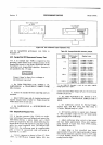
5.26.
DC VOLTMETER
INPUT
RESISTANCE TEST.
5-27.
A dc
standard
(hp-
7a0B) and a
I
MA
!O.l%
resistor
(-hp-
0698-6369) are required
for this
test.
Connect Guard to Input Low
or domage to
the instrument
may
result.
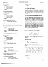
a. Connect
3490A,
dc
standard and
resistor
as
shown
in
Figure
5-5.
b. Set 3490A
FUNCTION to
DC, RANGE to
lOV.
c.
Connect
jumper
across
I M,fl
resistor as indicated.
Adjust
dc
standard
output to 10.0000V.
Note 3490A
reading.
d.
-Remove
jumper
from
I MQ resistor. 3490A
read-
ing should not change
more than
00.0010
V, verifying
input
resistance
) l0
ro
Q.
e.
Set
3490A RANGE to 100
V. Reduce input
to
1.00000 v.
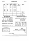
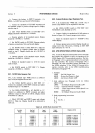
PEBFORMANCE CHECKS
AC
CALIERATOR
hp 7454
ELECTRONIC
COUNTER
hp
53OO
MULTIMETER
hp
349O4
CONN€CTEO
1O
CHASSIS
GROUNO
r-------l
oQ
I tlr
+T-F++F
U
l0
D
O
0 0
0 0 00
i@@@@@@
e
o@
oo
Figure
5-3.
AC Common-Mode
Rejection
Test.
<t