


(F
I
OUTGUARD REMOTE
03490-
665t2
A8J
IO
I
aa,rs
03490-66510
l<-
cABLE
w7
/
- -
f---
.
TSoLATED
REMOTE
:
ISOLATED BCD MODULE
MOOULE
03490- 60308
|
05490
-
60306
r-l
rffi
l_J
I
|
-J- --\
I'
I ;+CABLE
W4
i
.
___/
;<-caBLE
rY6
t\
-
E
TNGUARD BcD
JJiJV-99JWt
AI.J8
-_
f-1
AIJ
7
03490-56511
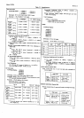
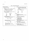
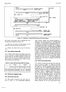
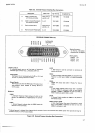
Figure 24.
Installation of lsolated BCD
Output
and Remote Options.
Model3490A
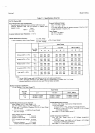
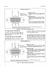
2-29. INTERFACE
CONNECTIONS.
2-30.
Data
0utput
0ption
021.
2-31.
Data
Output
connections
and logic
shown
in
Figure
2-5.
The
measurement
W7 between
this assembly
and
the
outguard
side
of the
Isolated
Remote Module
(see
Figure 24).
g.
Make sure all boards are seated
properly
and all
cables
are
securely
inserted in their connectors.
h. Replace top shield
and
top
cover
of
the
instru-
ment.
2-27.
Option 050 and
Option 060.
2-28.
A Model 34904
Option
050
(50
Hz
power
line)
can
be
converted
to an Option
060
(60
Hz
power
line)
;^.
and vice
versa.
Only
two parts
are different for these two
options. These
are
the Clock
Oscillator
crystal
and the
input
resistor in
the Integrator
circuit.
Table
2-1
shows
the
correct parts
for
each option.
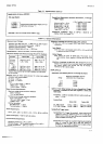
Table
2-1.
Option
050 and
Option 060
Part
Changes.
Crystal
A'1R207
Frequency
hp- Part
No Resistance+lp- Part No
Option 050
Option 06O
3.333 MHz
4.000
MHz
o4100466
0410{465
100
kfi
84.5 ko
07574465
0@8-4510
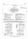
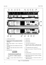
Section
Il
range, function, polarity
and overload information
is
contained in ten
four-bit
groups
of
l-248
BCD coded
information.
This
information
may be either
HIGH true
or
LOW true,
as selected
by the
HIGH/LOW switch
on
the
Outguard
Data
Output Assembly,
Al0.
In
addition,
a
Data Flag output
signal is provided
which
goes
HIGH
during a measurement
sequence.
The Printer
Hold input
line is HIGH
true.
while Hold and External Encode
are
LOW
true.
All
input and
output logic
levels are
as
shown
in
Figure
2-5. Outguard
ground (pin
50) is isolated
from
inguard circuit
common
and chassis (power
line)
ground
and may be floated
a
maximum of
40 V above chasis.
._.The
mating connector
for
the
rear
panel
Data
Output
connector J6
is
-hp-
Part No.
125l{086
(Amphenol
Output option.
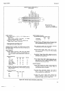
2-32. Remote
Gontrol
0ption 022.
2-33.
Remote
Control
input
and
output
lines
and logic
levels
are shown in
Figure 26.
Range
and
function
program
lines
are HIGH true,
while
all other
input
lines
are LOW
true.
The
Sample/Hold Mode, Delay
and
Trigger
lines
are for use
with the Sample/Hold
Option
040.
The Program
Flag
output is
HIGH during outguard-
to-inguard
transfer
of
program
information,
and the
Data Flag
output
is HIGH
during a
measurement
sequen@. The
Stretched
Pulse
Output
is
also
intended
for use with the
Sample/Hold
option.
All
input
and
output logic
levels
are as indicated
in Figure 2{.
Outguard
ground
(pins
7, ll
and 12) is isolated
from
inguard
common
and
chassis
(power
line)
ground
and
may
be floated
a maximum
of 40 V above chassis. The
mating
connector
for the
rear
panel
Remote Input
levels
are
magnitude,
:-J