


Model34904
Section
II
FE
lo
rE=ä;:
e
t:uE3X:I--
52 H *
F
E I =
6 s
i ä
"
qd
E
;
?
3
5 fr i F 3 ä
2-
39H;;5EEiF==
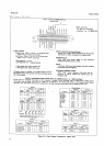
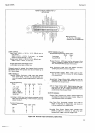
34904-B-296a
LOGIC LEVELS
.
lnput Lines:
HIGH
=
+
3.9
V
t
1.5
V,
100
pA
rnax;
or
open
circuit
LOW
=
+
0.3 V
I
0.3 V,
2 mA rnax.; or
contact
closure to
ground
through
<
300
A.
Output
Lines: HIGH
=
+
39 V
j
i.S
V, 400
pA
nnx.
LOW
=
+
0-3 V
1
0.3 V,
15 mA max.
H
after signal name
means HIGH
is true.
L
after
signal
name
means LOW
is
true.
Outguard
ground
is isolated
from
inguard circuit
common
and chassis
(power
linel
ground
and
may be
floated
up to
40
V
above chassis.
INPUT
SIGNALS
Remote
Enable:
Continuous
LOW input level
disables
front
panel
Range,
Function,
and
Sample/Hold con-
trols
and
enables
remote
programming
of
these func-
tions.
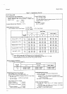
Range Programming:
Range
lnput
Logic
Levels
Test
No.
CBA
.1 V,.1
ksl
H H
L
2
lV,
1KO
H L
H
3
10v,
10ko
H
L
L
4
100v.
100ko
L H
H
5
1000v,1000ko
L H
L
6
10,000ko
L L
H
7
Autoränge:
HIGH input
level
selects
autorange
and
dis-
ables
range
programming.
In
Test Function.
autorange
selects
Test
No. 1.
Function
Programming:
Function
Input
B
DCL
'rlL
ACH
Test
H
Logic
Levels
A
L
H
L
H
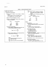
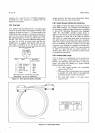
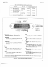
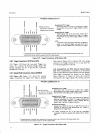
REMOTE INPUT
CONNECTOR J7
oPTtoN 022
Mating
Connector:
-hp-
Part
No.
1251
{O84
Amphenol
No.
57-3Ob00-37S
INPUT
SIcNALS
(Cont'd)
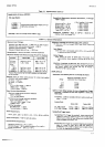
Sample/Hold
Programming
(Option
O40):
Mode
Delay
Track/Hold
L
H
Acquire/Hold L
L
Program
Execute:
LOW input
level
for
minimum
of
5 ms
initiates
outguard-to-inguard
transfer
of
Range,
Func_
tion,
and
Sample/Hold
program
information.
Hold: Continuous
LOW input
level
disables
autornltic
sampling and
permits
external
triggering.
External
Encode
(Trigger:
When
,,Hold,,
mode
is serec_
ted,
"0"
input
level for
minimum
of
24O
ps
initiates
one reading
cycle.
Sample/Hold
Trigger
(Option
O4O):
LOW input
levet
for
.*'
minirpum
of
30
ns
triggers
Sample/Hold
circuits
and
Stretched Pulse
Output circuit.
iL.
S/H AC Trigger
(Option
040):
Negativegoing
edge
of an
input
pulse
at
least
30
ns
wide and
having
an
ampli-
tude
from
2
V
to 15
V triggers
Sample/Hold
circuits
and
Stretched Pulse
Output circuit.
OUTPUT
SIGNALS
Program
Flag:
Changes
from
LOW to H|GH
at
beginning
of outguard-to-inguard
information
transfer.
Return to
LOW
indicates
transfer
is
complete.
Data Flag
(Print
Commandl:
Changes from
LOW to
HIGH at
beginning
of
measurement,
and returns
to
LOW
at
completion
of
a reading
cycle.
Stretched
Pulse
Output
(Option
04Ol:
Changes
from
Hf
GH
to
LOW for
a
minimum
ot
24O
tts
for
each
Sample/Hold
Trigger
or
S/H AC
Trigger input.
ä-j=!9il
äEHäEä
t:Litr
EF!!A
= Ir
*
qc
-
.<
=a
*
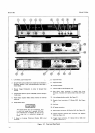
Figure
2-6. Remote
Input
Connestions,
Option
022.
2-5