


Section
II
connector
J7 is
-hp-
Part
No.
l25l{084
(Amphenol
57-30360-375).
This
connector is supplied
with the
Remote
Control
option
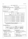
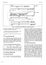
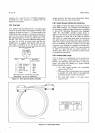
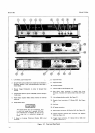
2-34. Rear
Input.
2-35. Options
020 and
030
provide
a rear
panel
input
connector
in
parallel
with the front panel
terminals. This
connector
is shown
in Figure 2-1
.
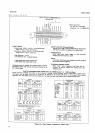
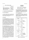
The
inner
guard
of the
3490A Rear Input
connector is internally connected
to
pin
B.
Do not connect these
points
together externally.
The
mating
connector
for this rear
panel
input is
-hp-
Part No. 125l-1233, Component Manufacturing
Service,
Inc. Part
No. A-1369. A six-foot
cable,
-hp
Part
No.
03490-61612, is
supplied with Options
020 and 030.
This cable
is terminated
at
one end
by the rear input
Model 3490A
mating
connector; the other
end
is unterminated.
Figure
2-7
also shows the wire
colors
in this cable.
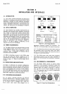
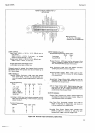
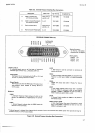
2-36.
General
Purpose
lnterface
Bus
Connections.
2-37
. Figure
2-9 shows the signal connections
at the
rear
panel
GPIB connector, Il2,
and.
gives
a
brief
description
of each
signal. Additional
signal information
is
included
in
Section
III,
Operating Instructions
(see
Paragraph
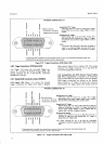
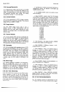
3-90). The
1063IA/B/C
Interface Cables
shown
in
Figure
2-8 are
used to connect
the
instruments
together.
The
connectors
at either
end of the
cable
are
identical
and consist
of a
plug
which mates with the instrument
rear
panel
connector
or another cable, and a
receptacle
which
will receive
another
cable
plug.
Instruments
may
.then
be
paralleled
as
shown
in Figure
4-20. The
dual
connector
is not
available as
a
separate
unit because
the
hood is
molded
around the
cable.
The connectors
listed
in Table
2-2
mate with the
rear
panel
connector
or
another cable. These
do
not
provide
the
thumb
screws
for securing
the connectors.
2-38.
Interface
Gable
Length.
2-39. As many
as
15 instruments can be connected
in
parallel
to
the same
General
Purpose Interface
bus;
however,
the following
restrictions must be observed.
Figure
4-20 shows the
cabling
for
a
typical
General
Purpose
Interface
bus system.
l. The cable length between
two instruments
cannot exceed 12 feet.
2. When
more
than two instruments
are
connected
in
parallel,
the
cable
length to
each additional
instrument
cannot
exceed
6
feet
per
unit.
3.
The total
cable
length to
all
units
cannot
exceed 5 I
feet.
A
B
c
D
tr
r
Rear Input
Connector,
J10
Signal
)
High\
o
Sisnal
or
LoryJ
Ext.
Ref.
Input Low
Input High
Conn. to B
(lnt)
Guard
Wire Color
(External
Cable)
White
Green
Black
Fled
NC
Shield
Mating Connector:
-hp-
Part
No.
1251-1233
Mating
Cable:
-hp-
Part No.03490-61
612
Figure 2-7. Rear Input Connector and Cable.
CABLE
PART
NO.
LENGTH
10631A
106318
10631C
3ft
6ft
'l2tt
Figure
2-8. Interface Bus Cables.