


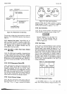
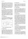
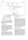

INPUT
ATTENUATOR
CONVERTER
AMP RECTIFIER
rNeur{
?M
K?
OUTPUT
DC
AMP
3490A-A-2824
50K
FEEDBACK
ATTENUATOR
DC
FEEDBACK
AMP
25oK
FI
LTER
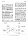
Model
34904
Figure
4-6.
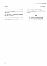
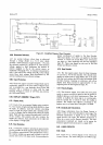
Table
4-1. AC Amplifier
Ranging.
Range
I
nput
Attenuator
Amplifier
Gain
Total
Gain
1V
10v
1(X)
v
1000 v
1
1
0.o1
0.01
1
o.1
1
0.1
1
0.1
0.01
o.001
a
gain
of
I
or
gain
of 0.1 may be
selected. DC
feedback
stabilization
is
provided
through
an
integating amplifier.
Saturation
of
the
Converter
Amplifier
is
prevented
by
a
diode
protection
circuit
which
limits the output
to
approximately
1
7 V
peak.
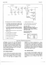
&58. Rectifier
and Filter.
zt-59.
The
output of the
Converter
Amplifier
is
rectified
by a half-wave
rectiher,
resulting
in
a
positive
output. A
complementary
diode
in
parallel
with
the
output
recti-
fier diode
is used to provide
a
full-wave
ac
feedback
to
the
amplifier input.
Active filtering is
used so that the
necessary
filtering
can
be
obtained
with
capacitors of a
practical
size. In
ac
measurements, the output of
the
converter is
applied through
a FET switch
(E
in Figure
44)
Io the
DC
Amplifier
during run-up.
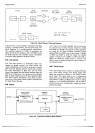
4.60.
OHMS
CONVERTER.
461. The
Ohms
Converter
supplies
a reference
current
through
the
resistance
being
measured.
The resulting
voltage
drop, which
is proportional
to
the
resistance,
is
measured
in the
same
manner
as
a dc
voltage input,
except that the Q
Reference
is
used for run-down. A
resistance measurement,
then,
is
the
ratio of
the
voltage
developed
across the
unknown
resistance, to the
Q
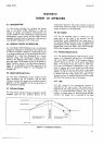
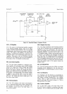
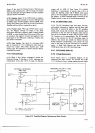
Section
IV
Simplified
Diagram, AC
Conyerter.
Reference voltage.
A simplified diagam
of the
Ohms
Converter
is shown in
Fizure 4-7.
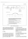
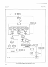
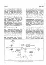
4-62.
Current
Source.
443. One
input of the
operational
amplifier
in
the
current source
is referenced
to
ground.
The
,fl
Reference
voltage
(approximately
-
I V) is
applied
to
the
other
input
through
a reference resistance, Rr.1, whose
value
is
selected
according
to the ohmmeter range. The
nature
of
an operational
amplifier
is such that it
tends to
maintain
both inputs
at
the same potential. This
requirement
cannot
be satisified by cunent drawn from
the
FET
input;
consequently,
it must be met by
the
feedback
current, which
passes
through the resistance being
-
measured, R1. As the amplifier output
goes
negative
because df the negative input, the
transistor
at
its output
'"'
is forward biased.
The
resulting feedback current is
automatically adjusted by
the
amplifier
to cause
a
I
V
drop across R.e;. The value of
the
current,
then,
is
inversely
proportional
to the
value
of R1s1.
464. 0hmmeter
Power
Supply.
4-65. An
output
from
the
State Clock
(see
Logic
Circuits)
is applied
to
a divide
by six
counter.
The
counter output is
then
applied
to
both
ends'of a
center-tapped
transformer
primary.
(The
signal
at one
end
is inverted
and
the
other
is not.) The
output of
the
transformer
secondary is rectified by
a full-wave recti-
fier, and
this floating
voltage
is used as a
supply for the
Ohms
Converter circuits.
This
permits 4-terminal resis-
tance
measurements,
since the
A
Sipal
Low
is not
internally connected to circuit
common during run-up.
The
Ohmmeter
Power
Supply
is
disabled
during
all
measurements except resistance
measurements.
+7