


Section
III
3-70.
The
Data
Flag
@rint
Command) output signal
changes
from LOW to HIGH at
the
beginning
of a
measurement, and returns
to LOW at
the completion of
a reading
cycle. If the
instrument is
operating
in the
autorange
mode, Data
Flag
remains
HIGH until after one
reading
has been completed on
the correct range. The
HIGH to LOW
transition constitutes a Print Command
signal to a digital recorder.
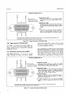
3-71.
Input
Signals
and
Levels.
3-12. Three input connections
are
available
at
the Data
Output
connector. The input logic HIGH
=
+
3.9 V
+
1.5V, l00pA max, or
an
open circuit. The
LOW
level
=
+
0.3 V
t
0.3 V.
2 mA max.
or
contact closure to
ground
through <
300
A.
A HIGH
input at the Printer
Hold connection causes the 3490A to stop
automatic
sampling
until
the
line returns to
LOW.
A continuous
LOW
connection
at
the Hold input
prevents
automatic
sampling
and
permits
external triggering. When
Hold
is
LOW,
a
LOW input
level
at
the External Encode input
for
a mimimum of 240
ps
initiates
one reading
cycle
(see.
Paragraph
3-64).
3-73.
Data
0utput
lsolation.
3-74. Nl output
and
input lines at the Data Output
connector are isolated from
the internal
(inguard)
circuits
and from the input
terminals. The instrument
will
maintain
all
normal-
and
common-mode rejection
characteristics
with
the
Data Output
lines properly
connected.
Outguard
ground
is
isolated
from
inguard
common
and from chassis
(power
line)
ground
and may
be floated up to 40
V above
chassis.
3-75.
REMOTE
C0NTROL
(0ption
022).
3-76. In
addition to
remote control
of range
and
iunction. the Remote
Control option
includes provision
for
external
triggering.
A Program Flag output is HIGH
during
remote
program
execution, and
the Data Flag
rrulput
is
HIGH
during
a measurement
se,quence.
A
:natinE
connector.
*rp- Part No. 125 l-0084
(Amphenol
\-' r:-3036G375)
is suppliedwith
the Remote Control
.t
ol:on.
la
Model34904
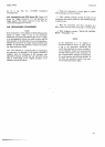
3-77.
Input
Signal
Requirements.
3-78. The Remote
Control
option
permits
remote
selec-
tion
of the remote
mode
of
operation,
and remote
programming of
range and
function,
including
Test and
optional Sample/Hold.
For
input
signals,
the
logic
HIGH
level
=
+
3.9 V
r
1.5
V,
100
pA
max.,
or an
open
circuit. The LOW
level
=
+
0.3
V
t
0.3 V,
2 mA max.,
or
contact
closure to
ground
through
<300 O.
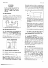
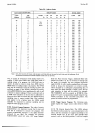
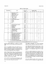
Figure 26
shows the binary
coding required
for range
and function
programming,
as well as
the requirements
for the other
input
signals.
3-79.
0utput Signals.
-3-80.
The
Program
Flag output
changes from LOW
to
HIGH at
the beginning
of outguard-to-inguard
transfer
of
program information, and
returns
to LOW to
indicate
the
transfer is
complete
and
the
instrument
is ready for
a
measurement.
The
Data Flag output
changes from LOW
to
HIGH
at
the beginning
of a measurement,
and returns
to LOW at
the completion
of a
reading cycle.
If the
instrument
is operating in
the autorange mode,
Data
Flag remains
at HIGH until
one reading has
been
completed on
the correct
range. The
logic levels for
output
signals
are
as follows: HIGH
=
+
3.9 V
t
1.5 V,
400
l,rA
max; LOW
=
+
0.3
V
r
0.3
V,
l5
mA max.
3-81.
Remote Programming
Procedure.
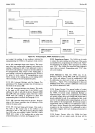
3-82.
All
program
input
lines
are
HIGH unless forced
LOW by an external connection.
The Remote
Enable
line
must be held
LOW continuously.
If
it returns to
HIGH, range and
function
program
capability reverts to
the
front
panel
controls. The remote
program
sequence
is shown in Figure 3-6.
3-83.'Remote Gontrol 0f
Test Function.
3{4. The Test function may be
selected remotely by
programming Function
A and
B
HIGH.
Test No.
1,
Logic Test, is selected
by
programming the
Autorange
line HIGH. Tests
No. 2 through 7 are selected
by
programming
Range lines A, B and C as
indicated
in
Figure
2-6.
When Test No. I is selected, a minimum
of
l0 readings must be
taken to
record all
the test data
before changing
the program. In
Test No.
3,
a minimum
of two
readings
is required to record the turnover
error
test. For
all
other
tests,
only one reading
is
necessary.
Paragaph 3-38
describes
the internal tests. The
-
10 V
input
required
for Test No.
6,
and
the Q
signal
short
required for Test No. 7 may be applied
throughout
the
test sequence without affecting the other
tests. In Test
No.
4, the ratio
reference
check
cannot
be
controlled
remotely.
3-85.
Remote Control
lsolation.
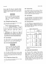
336. All input
and output lines at
the Remote
Input
connector
are
isolated from the
internal
(inguard)
circuits
and
from
the input termina-ls. The
instrument
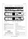
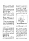
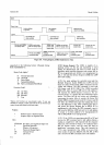
Column
10
-_-_ll-
947654321
0v3012300
l+
I
Numerical
I
Readino
L
*"nn"
F unction
Polarity/Overload
Sample/Hold
Mode
Figure
3-5. Option
021
Printout.