


3 - 41
3. CC-LINK COMMUNICATION FUNCTIONS
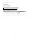
3.7 Function-by-function programming examples
This section explains specific programming examples for servo operation, monitor, parameter read and write,
and others on the basis of the equipment makeup shown in section 3.7.1.
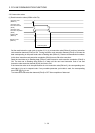
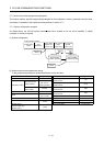
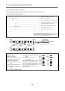
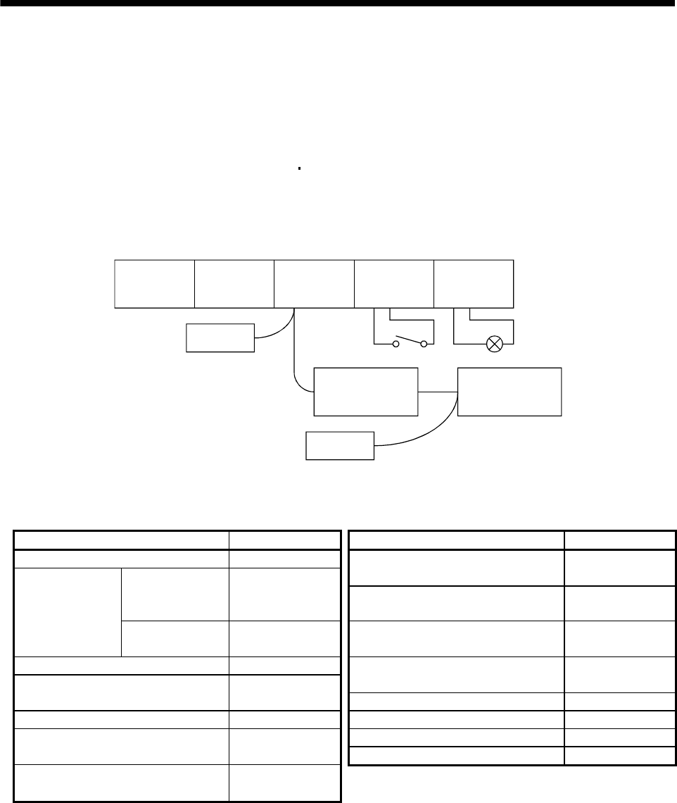
3.7.1 System configuration example
As shown below, the CC-Link system master
local unit is loaded to run two servo amplifiers (1 station
occupied / 2 stations occupied).
(1) System configuration
Input module
QX40
(X20 to X2F)
Master station
QJ61BT11N
(X/Y00 to 1F)
CPU
Q02HCPU
Power supply
Q62P
Programmable controller
Servo amplifier
(1 station occupied)
Station No.1
Output module
QY40P
(Y30 to Y3F)
Terminating
resistor
X20 to Y30
Station No.2
Terminating
resistor
Servo amplifier
(2 stations occupied)
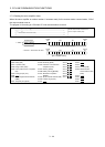
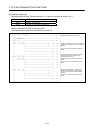
(2) Master station network parameter setting
In the programming examples, network parameters are set as below.
Item Setting condition Item Setting condition
Start I/O No. 0000 Remote register (RWr)
Clear Refresh device
W0
Operational setting
Data link disorder
station settings
(No check on
"Hold input data")
Remote register (RWw)
Refresh device
W100
Case of CPU Special relay (SB)
STOP setting
Refresh
Refresh device
SB0
Type Master station Special relay (SW)
Remote net Refresh device
SW0
Mode
(Ver.1 mode) Retry count 3
All connect count 2 Automatic reconnection station count 1
Remote input (RX) CPU down select Stop
Refresh device
X1000
Scan mode setting Asynchronous
Remote output (RY)
Refresh device
Y1000