


14 - 44
14. OPTIONS AND AUXILIARY EQUIPMENT
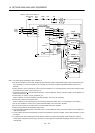
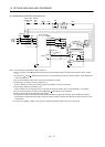
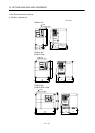
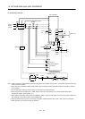
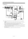
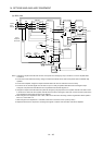
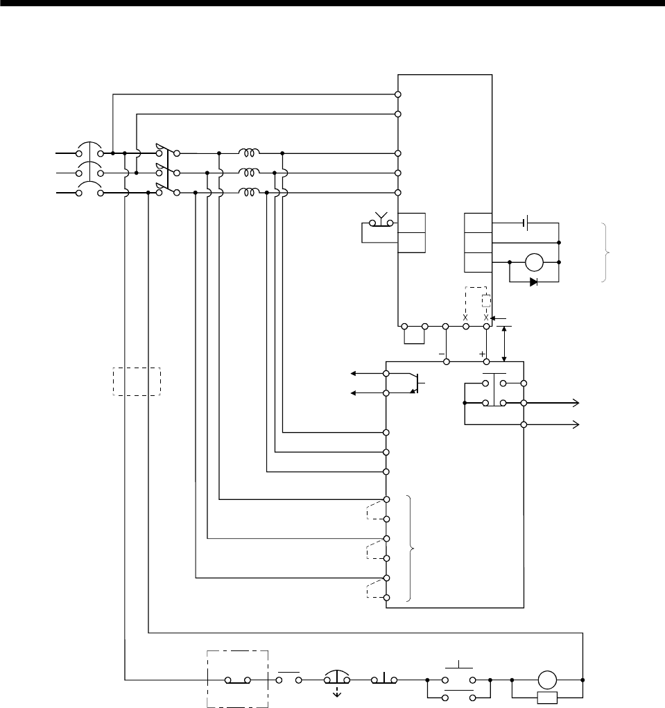
(2) Connection example
(Note 7)
Power
supply
NFB
MC
Servo amplifier
L
11
L
21
L
1
L2
L
3
SK
ON
MC
BC
NPC
RDY
SE
Alarm
output
RDY
output
A
B
C
5m or less
Operation ready
MC
OFF
EMG
ALM
RA
FR-RC-(H)
Ready
Power factor improving reactor
FR-BAL
R/L
1
S/L2
T/L
3
B
C
RRX
R
SX
S
TX
T
Phase detection
terminals
(Note 1)
Power regeneration
converter FR-RC-(H)
N/
P/
EMG
RA
DOCOM
DICOM
ALM Trouble
(Note 3, 5)
DOCOM
Forced
stop
24VDC
P
2
P
1
(Note 4)
(Note 2)
CN6 CN6
(Note 6)
Note 1. When not using the phase detection terminals, fit the jumpers across RX-R, SX-S and TX-T. If the jumpers remain removed, the
FR-RC-(H) will not operate.
2. When using servo amplifiers of 5kW and 7kW, always remove the lead of built-in regenerative resistor connected to P terminal
and C terminal.
3. For sink input-output interface. Refer to section 4.8.3 for source input-output interface.
4. When using the servo amplifier of 11k to 22kW, always connect P
1
and P. (Factory-wired.) When using the power factor
improving DC reactor, refer to section 14.11.
5. When setting not to output Trouble (ALM) with parameter change, configure power supply circuit for turning magnet contactor off
after detecting an occurrence of alarm on the controller side.
6. Stepdown transformer is required for coil voltage of magnetic contactor more than 200V class in 400V class servo amplifiers.
7. Refer to section 1.2 for the power supply specification.