


4 - 26
4. SIGNALS AND WIRING
Device Symbol
Connector
pin No.
Functions/Applications
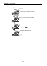
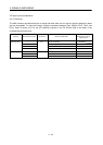
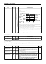
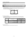
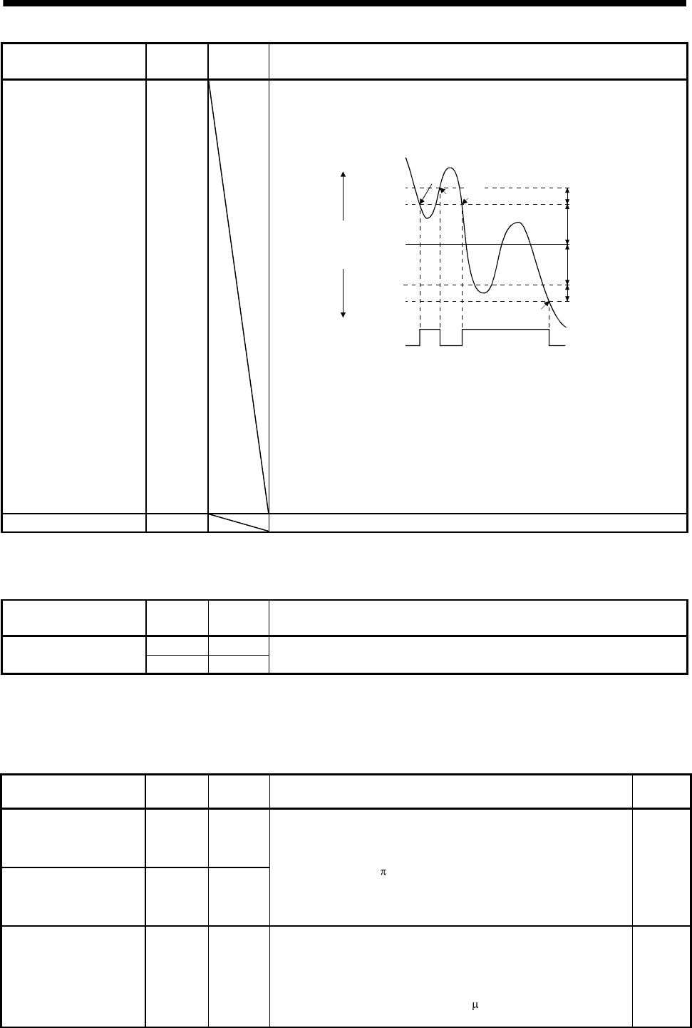
Zero speed ZSP
ZSP turns on when the servo motor speed is zero speed (50r/min) or less. Zero
speed can be changed using parameter No.PC17.
Example
Zero speed is 50r/min
OFF
ON
0r/min
1)
3)
2)
4)
Forward
rotation
direction
Servo motor
speed
Reverse
rotation
direction
zero speed
(ZSP)
ON level
50r/min
OFF level
70r/min
ON level
50r/min
OFF level
70r/min
Parameter
No.PC17
20r/min
(Hysteresis width)
20r/min
(Hysteresis width)
Parameter
No.PC17
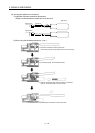
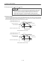
ZSP turns on 1) when the servo motor is decelerated to 50r/min, and ZSP turns
off 2) when the servo motor is accelerated to 70r/min again.
ZSP turns on 3) when the servo motor is decelerated again to 50r/min, and turns
off 4) when the servo motor speed has reached -70r/min.
The range from the point when the servo motor speed has reached ON level, and
ZSP turns on, to the point when it is accelerated again and has reached OFF
level is called hysteresis width.
Hysteresis width is 20r/min for this servo amplifier.
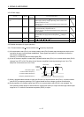
Variable gain selection CDPS CDPS is on during gain changing.
Note. These are pin Nos. assigned at default.
4.5.2 Input signals
Device Symbol
Connector
pin No.
Functions/Applications
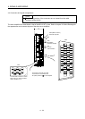
PP CN6-6 Manual pulse generator
NP CN6-19
Used to connect the manual pulse generator (MR-HDP01). (Refer to section
14.18.)
4.5.3 Output signals
Refer to section 4.8.2 for the output interfaces (symbols in the I/O Division field in the table) of the
corresponding connector pins.
Signal Symbol
Connector
pin No.
Functions/Applications
I/O
division
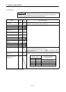
Encoder A-phase pulse
(differential line driver)
LA
LAR
CN6-11
CN6-24
Encoder B-phase pulse
(differential line driver)
LB
LBR
CN6-12
CN6-25
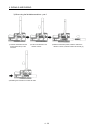
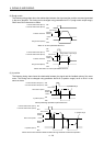
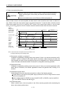
Outputs pulses per servo motor revolution set in parameter No.PA15
in the differential line driver system. In CCW rotation of the servo
motor, the encoder B-phase pulse lags the encoder A-phase pulse
by a phase angle of
/2.
The relationships between rotation direction and phase difference of
the A- and B-phase pulses can be changed using parameter No.
PC19.
DO-2
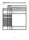
Encoder Z-phase pulse
(differential line driver)
LZ
LZR
CN6-13
CN6-26
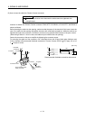
Outputs the zero-point signal of the encoder in the differential line
driver system. One pulse is output per servo motor revolution. This
signal turns on when the zero-point position is reached. (Negative
logic)
The minimum pulse width is about 400
s. For home position return
using this pulse, set the creep speed to 100r/min. or less.
DO-2