


12 - 7
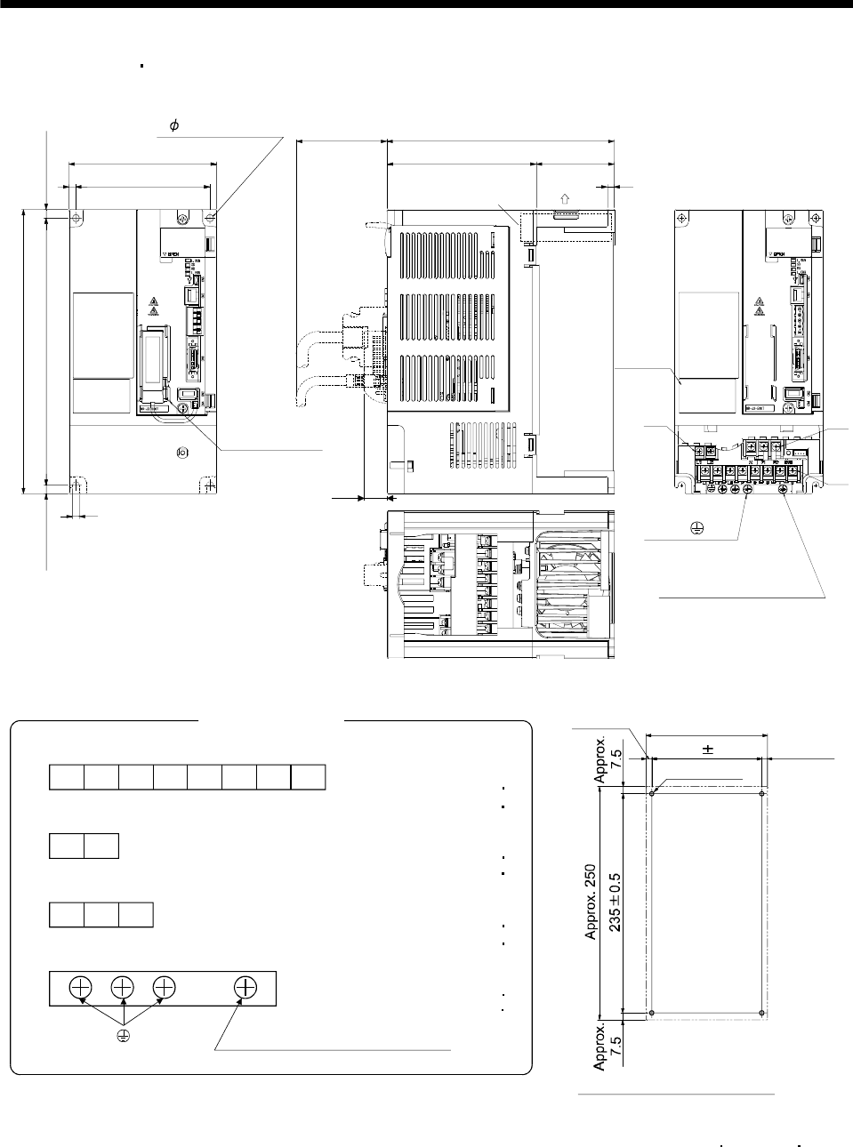
12. OUTLINE DRAWINGS
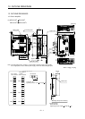
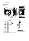
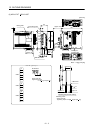
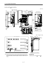
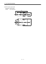
(7) MR-J3-350T4
MR-J3-500T(4)
[Unit: mm]
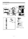
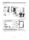
3 places for
ground (M4)
With MR-J3BAT
Terminal layout
(Terminal cover open)
2- 6 mounting hole
Built-in regenerative
resistor lead terminal
fixing screw
130
1186
Approx. 7.5
Approx. 7.5
250
235
6
200
Approx. 80
131.5 68.5
Cooling fan
wind direction
6
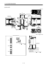
TE1
TE2
TE3
20.5
Rating
plate
CHARGE
Cooling fan
Mass: 4.6 [kg] (10.1 [lb])
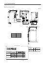
VW
TE2
N
L
11
L
21
TE3
L
1
L
2
L
3
P
TE1
Terminal screw: M4
Tightening torque: 1.2[N m]
Terminal signal layout
PE terminal
CU
P1 P2
Built-in regenerative resistor lead
terminal fixing screw
Terminal screw: M3.5(Note)
Tightening torque: 0.8[N m]
Terminal screw: M4
Tightening torque: 1.2[N m]
Terminal screw: M4
Tightening torque: 1.2[N m]
(10.6 [lb in])
(7.08 [lb in])
(10.6 [lb in])
(10.6 [lb in])
Note. Screw size is M3.5 for the control circuit terminal block (TE2) of the servo
amplifier manufactured in April 2007 or later. Screw size is M3 for the control
terminal block (TE2) of the servo amplifier manufactured in March 2007 or
earlier.
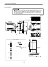
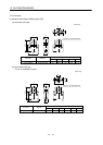
4-M5 screw
Approx. 6
Approx. 130
118 0.5
Mounting hole process drawing
Mounting screw
Screw size: M5
Tightening torque: 3.24[N m] (28.7[lb in])
Approx. 6