


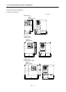
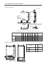
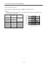
14 - 37
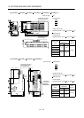
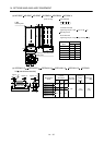
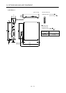
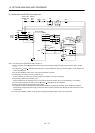
14. OPTIONS AND AUXILIARY EQUIPMENT
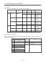
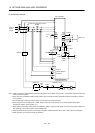
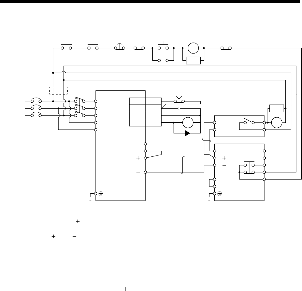
(2) Combination with MT-BR5-(H) resistor unit
NFB
(Note 9)
ALM
RA1
MC
SK
MC
ON
OFFEMG
Servo motor
thermal relay
RA2
(Note 1)
Power
supply
N/
P/
BUE
SD
PR
B
C
A
SD
MSG
(Note 3)
(Note 6)
RA3
17
5
EMG
DOCOM
DICOM
ALM
P
1
C
N( )
FR-BU2-(H)
MT-BR5-(H)
Servo amplifier
P
PR
TH2
TH1
(Note 5)
MC
RA3
(Note 7)
(Note 2)
1
(Note 9)
CN6
L
3
L
11
L
2
L21
L1
SK
(Note 8)
24VDC
RA1
(Note 4)
(Note 10)
P( )
Note 1. For power supply specifications, refer to section 1.2.
2. Always connect P
1 and P( ) terminals (Factory-wired). When using the power factor improving DC reactor, refer to section
14.11.
3. Connect the P/
and N/ terminals of the brake unit to a correct destination. Wrong connection results in servo amplifier and
brake unit malfunction.
4. For the servo amplifier of 400V class, a step-down transformer is required.
5. Contact rating: 1a contact, 110VAC_5A/220VAC_3A
Normal condition: TH1-TH2 is not conducting. Abnormal condition: TH1-TH2 is conducting.
6. Contact rating: 230VAC_0.3A/30VDC_0.3A
Normal condition: B-C is conducting/A-C is not conducting. Abnormal condition: B-C is not conducting/A-C is conducting.
7. Do not connect more than one cable to each P(
) and N( ) terminals of the servo amplifier.
8. Always connect BUE and SD terminals (Factory-wired).
9. The diagram is for when outputting the trouble (ALM) is enabled by changing the parameter. When disabling to output the
trouble (ALM), configure the power supply circuit to turn off the magnetic contactor after detecting an alarm occurrence on the
controller side.
10. For the servo amplifier of 22kW, do not connect a supplied regenerative resistor to the P and C terminals.