


4 - 31
4. SIGNALS AND WIRING
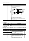
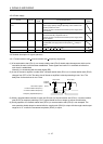
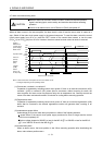
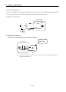
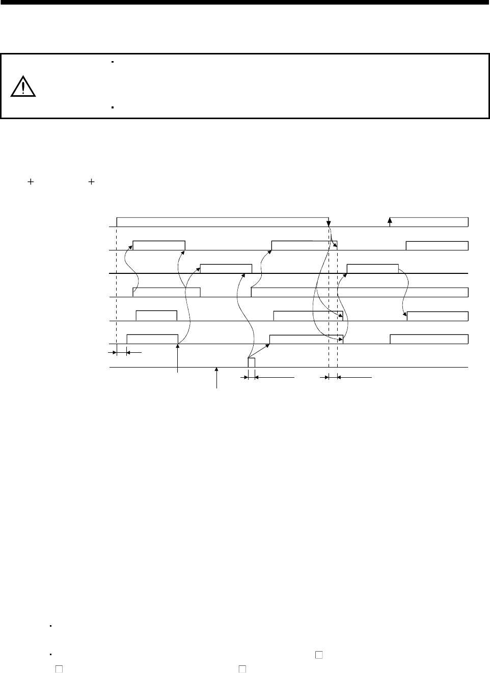
4.7 Alarm occurrence timing chart
CAUTION
When an alarm has occurred, remove its cause, make sure that the operation
signal is not being input, ensure safety, and reset the alarm before restarting
operation.
As soon as an alarm occurs, turn off Servo-on (RYn0) and power off.
When an alarm occurs in the servo amplifier, the base circuit is shut off and the servo motor is coated to a
stop. Switch off the main circuit power supply in the external sequence. To reset the alarm, switch the control
circuit power supply from off to on, press the "SET" button on the current alarm screen, or turn the reset
(RY(n
1)A or RY(n 3)A) from off to on. However, the alarm cannot be reset unless its cause is removed.
ON
OFF
ON
OFF
ON
OFF
ON
OFF
ON
OFF
ON
OFF
Brake operation
50ms or more
15 to 60ms (Note 2)
Alarm occurs.
Remove cause of trouble.
Brake operation
Power off
Power on
Valid
Invalid
Main circuit
control circuit
power supply
Base circuit
Dynamic brake
Servo-on
(RYn0)
Reset
(RY(n+1)A
or RY(n+3)A)
Ready
(RD)
Trouble
(ALM)
(Note 1)
1.5s
Note 1. Shut off the main circuit power as soon as an alarm occurs.
2. Changes depending on the operating status.
(1) Overcurrent, overload 1 or overload 2
If operation is repeated by switching control circuit power off, then on to reset the overcurrent (A32),
overload 1 (A50) or overload 2 (A51) alarm after its occurrence, without removing its cause, the
servo amplifier and servo motor may become faulty due to temperature rise. Securely remove the
cause of the alarm and also allow about 30 minutes for cooling before resuming operation.
(2) Regenerative alarm
If operation is repeated by switching control circuit power off, then on to reset the regenerative (A30)
alarm after its occurrence, the external regenerative resistor will generate heat, resulting in an
accident.
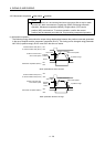
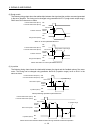
(3) Instantaneous power failure
Undervoltage (A10) occurs when the input power is in either of the following statuses.
A power failure of the control circuit power supply continues for 60ms or longer and the control
circuit is not completely off.
The bus voltage dropped to 200VDC or less for the MR-J3- T, to 158VDC or less for the MR-J3-
T1, or to 380VDC or less for the MR-J3- T4.
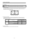
(4) Incremental system
When an alarm occurs, the home position is lost. When resuming operation after deactivating the
alarm, make a home position return.