


1 - 3
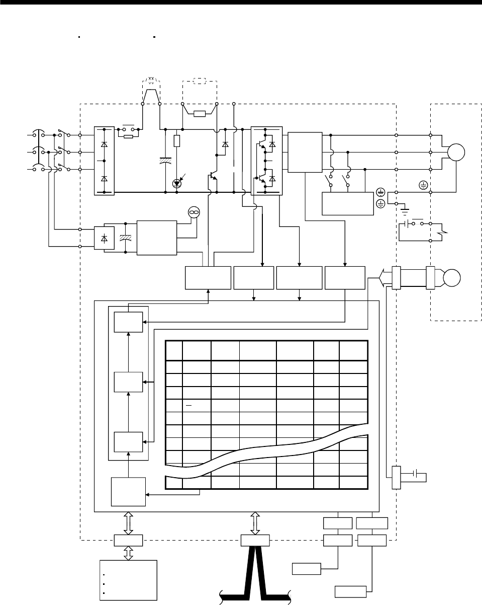
1. FUNCTIONS AND CONFIGURATION
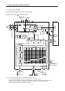
(2) MR-J3-350T4
MR-J3-500T(4) MR-J3-700T(4)
RS-422
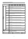
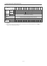
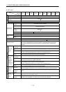
1 1000 1000 80 80 0 0
2
2000 2000 100 100 0 0
3
4000 2000 70 60 500 1
4
500 2000 60 70 1000 1
5
2000 80 80 0 0
6
2000 1000 80 80 0 0
7
1000 1000 80 80 0 0
8
1000 1000 100 100 0 0
1000 1000 100 100 0 0
255 2000 2000 80 80 0 0
1000
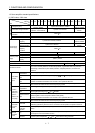
No.
Position
data
Speed
Acceleration
time
constant
Deceleration
time
constant
Dwell Auxiliary
Point table
Current
control
Speed
control
Position
control
Model adaptive control
Position
command
creation
(Note 2)
L
1
L2
L
3
MCNFB
Cooling fan
Base
amplifier
CN4
N
C
Encoder
Current
detection
L11
L
21
U
V
W
Power factor
improving DC
reactor
Regenerative
option
MR-J3BAT
P
1
P
2
(Note 1)
Power
supply
CHARGE
lamp
Regene-
rative
TR
Current
detector
Dynamic
brake
Electro-
magnetic
brake
Servo motorServo amplifier
Optional battery
(for absolute position
detection system)
Overcurrent
protection
Voltage
detection
Control
circuit
power
supply
CN2
P
U
V
W
M
Diode
stack
Controller
USB
CN3CN5
CC-Link
USB
Personal
computer
DI/O Control
Servo on
Start
Failure, etc
RS-422
CN1CN6
Relay
B2
B1
RA
24VDC
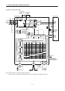
Note 1. Refer to section 1.2 for the power supply specification.
2. For the case when 2 stations are occupied. When 1 station is occupied, the point table ends at No.31.