


A - 8
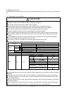
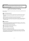
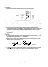
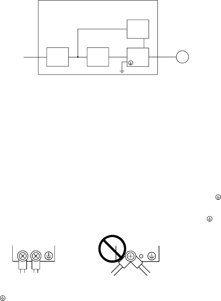
(2) Configuration
The control circuit provide safe separation to the main circuit in the servo amplifier.
NFB
MC
No-fuse
breaker
Magnetic
contactor
Reinforced
insulating type
24VDC
power
supply
Servo
amplifier
Servo
motor
Control box
M
(3) Environment
Operate the servo amplifier at or above the contamination level 2 set forth in IEC60664-1. For this purpose,
install the servo amplifier in a control box which is protected against water, oil, carbon, dust, dirt, etc. (IP54).
(4) Power supply
(a) This servo amplifier can be supplied from star-connected supply with earthed neutral point of
overvoltage category III set forth in IEC60664-1. However, when using the neutral point of 400V class
for single-phase supply, a reinforced insulating transformer is required in the power input section.
(b) When supplying interface power from external, use a 24VDC power supply which has been insulation-
reinforced in I/O.
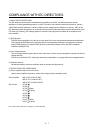
(5) Grounding
(a) To prevent an electric shock, always connect the protective earth (PE) terminals (marked
) of the
servo amplifier to the protective earth (PE) of the control box.
(b) Do not connect two ground cables to the same protective earth (PE) terminal (marked
). Always
connect the cables to the terminals one-to-one.
PE terminals
PE terminals
(c) If a leakage current breaker is used to prevent an electric shock, the protective earth (PE) terminals
(marked
) of the servo amplifier must be connected to the corresponding earth terminals.