


4 - 27
4. SIGNALS AND WIRING
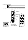
4.5.4 Power supply
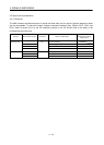
Signal Symbol
Connector
pin No.
Functions/Applications
I/O
division
Digital I/F power supply
input
DICOM CN6-5
Used to input 24VDC (24VDC
10% 150mA) for I/O interface. The
power supply capacity changes depending on the number of I/O
interface points to be used.
Connect the plus of 24VDC terminal external power supply for the
sink interface.
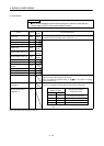
Digital I/F common DOCOM CN6-17 Common terminal for input signals such as DOG and EMG. Pins are
connected internally. Separated from LG.
Connect the plus of 24VDC terminal external power supply for the
source interface.
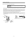
Open collector power input
OPC CN6-18 When using the MR-HDP01 manual pulse generator, connect OPC
and DICOMD, and supply OPC with the positive (
) voltage of
24VDC.
Control common LG CN6-23 Common terminal for the differential line driver of the encoder pulses
(LA
LAR LB LBR LZ LZR).
Shield SD Plate Connect the external conductor of the shield cable.
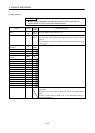
4.6 Detailed description of signals (devices)
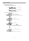
4.6.1 Forward rotation start
reverse rotation start temporary stop/restart
(1) A forward rotation start (RYn1) or a reverse rotation start (RYn2) should make the sequence which can be
used after the main circuit has been established. These signals are invalid if it is switched on before the
main circuit is established.
Normally, it is interlocked with the ready signal (RD).
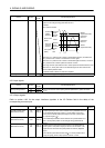
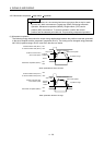
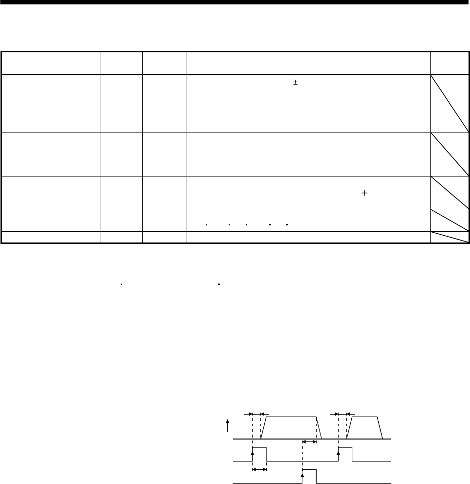
(2) A start in the servo amplifier is made when a forward rotation start (RYn1) or a reverse rotation start (RYn2)
changes from OFF to ON. The delay time of the servo amplifier's internal processing is max. 3ms. The
delay time of other devices is max. 10ms.
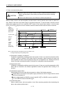
Servo motor speed
Forward rotation start (RYn1)
or reverse rotation start (RYn2)
Temporary stop/Restart (RYn7)
6ms or more
3ms or less 3ms or less
10ms
or less
Forward
rotation
0r/min
(3) When a programmable controller is used, the ON time of a forward rotation start (RYn1), a reverse rotation
start (RYn2) or temporary start/stop (RYn7) signal should be 6ms or longer to prevent a malfunction.
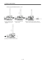
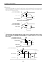
(4) During operation, the forward rotation start (RYn1) or reverse rotation start (RYn2) is not accepted. The
next operation should always be started after the rough match (RXn2) is output with the rough match output
range set to “0” or after the movement completion (RXnC) is output.