


6 - 32
6. PARAMETERS
No. Symbol Name and function
Initial
value
Unit
Setting
range
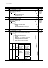
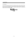
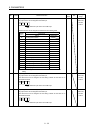
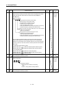
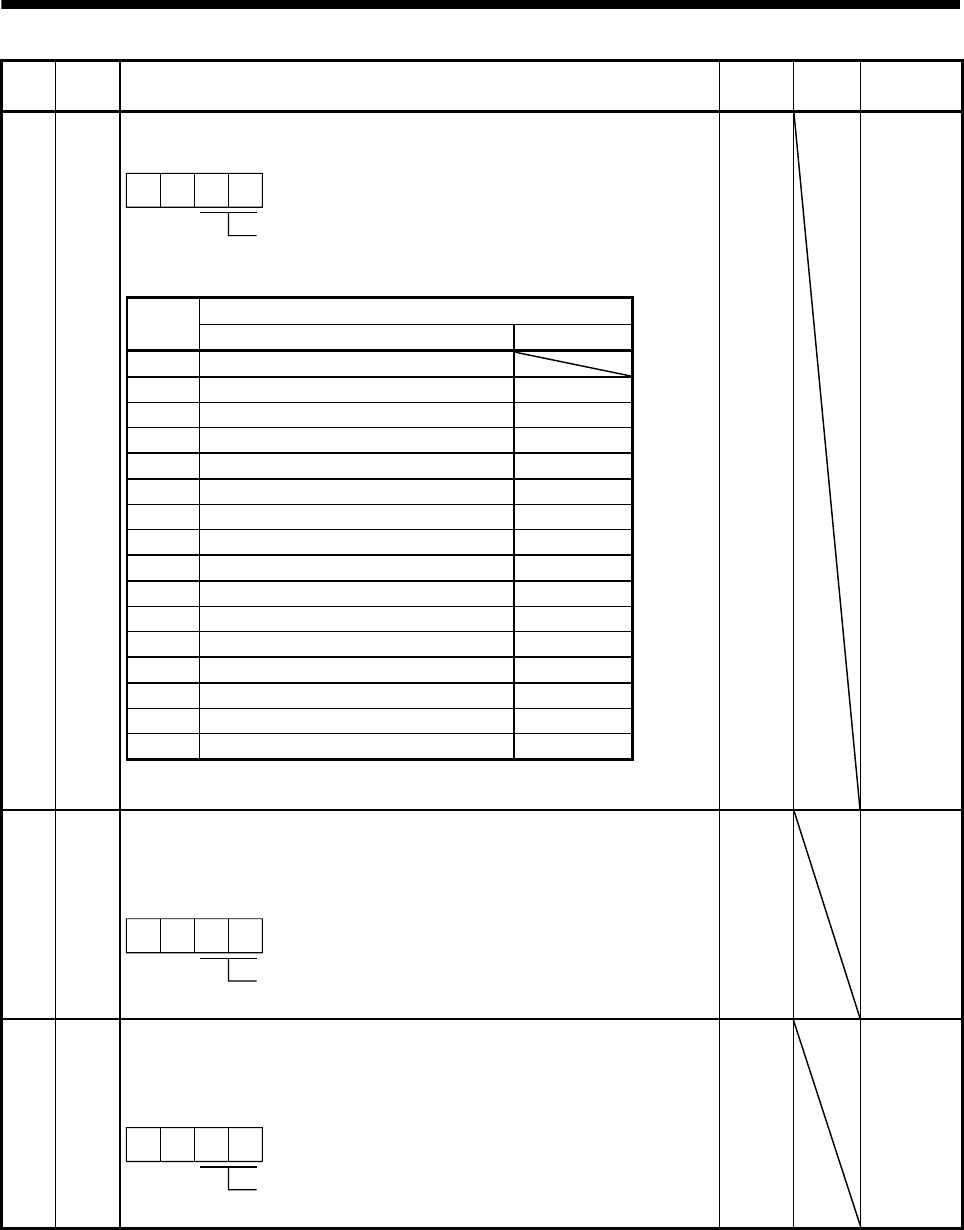
PD06 *DI2 Output signal device selection 2 (CN6-2)
Any input device can be assigned to the CN6-2 pin.
0
Select the input device of the CN6-2 pin
0
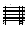
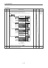
The devices that can be assigned are indicated in the following table.
Input device
Setting
(Note)
Name Abbreviation
00 No assignment function
02 Servo-on SON
03 Reset RES
04 Proportion control PC
06 Clear CR
07 Forward rotation start ST1
08 Reverse rotation start ST2
09 Internal torque limit selection TL1
0A Forward rotation stroke end LSP
0B Reverse rotation stroke end LSN
0D Gain changing CDP
20 Automatic/manual selection MD0
24 Manual pulse generator multiplication 1 TP0
25 Manual pulse generator multiplication 2 TP1
27 Temporary stop/restart TSTP
2B Proximity dog DOG
Note. The other setting values than shown in this table are for manufacturer
setting.
002Bh Refer to
name and
function
column.
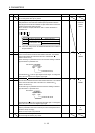
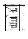
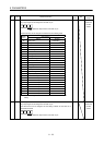
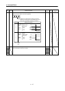
PD07 *DI3 Output signal device selection 3 (CN6-3)
Any input device can be assigned to the CN6-3 pin.
The devices that can be assigned and the setting method are the same as in
parameter No.PD06.
0
Select the input device of the CN6-3 pin
0
000Ah Refer to
name and
function
column.
PD08 *DI4 Output signal device selection 4 (CN6-4)
Any input device can be assigned to the CN6-4 pin.
The devices that can be assigned and the setting method are the same as in
parameter No.PD06.
0
Select the input device of the CN6-4 pin
0
000Bh Refer to
name and
function
column.