


3 - 3
3. CC-LINK COMMUNICATION FUNCTIONS
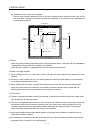
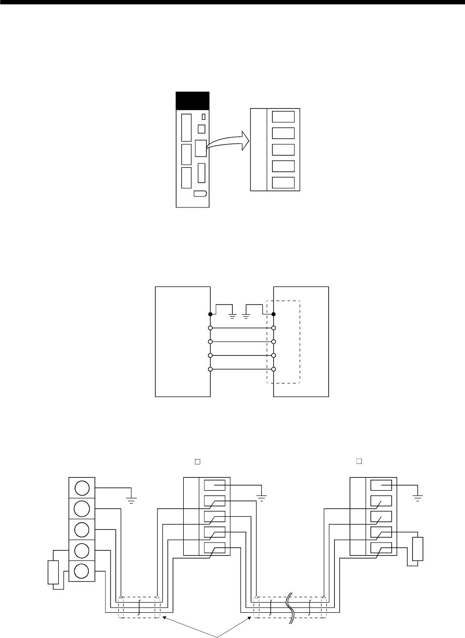
3.2.2 Wiring method
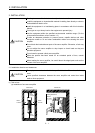
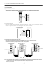
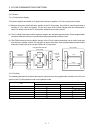
(1) Communication connector
The pin layout of the communication connector CN10 on the servo amplifier unit is shown below.
DA DGDB SLD FG
Servo amplifier
CN1
CN1
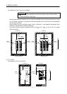
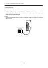
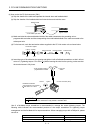
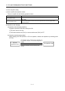
(2) Connection example
The servo amplifier and programmable controller CC-Link master unit are wired as shown below. Refer to
section 14.9 (3) for the CC-Link Ver.1.10-compliant cable used for connection.
Servo amplifier
SLD
FG
DA
DG
SLD
DB
CN1
FG
DG
DA
DB
Programmable controller
CC-Link master unit
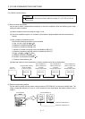
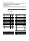
(3) Example of connecting multiple servo units
As the remote I/O stations of CC-Link, servo amplifiers share the link system and can be
controlled/monitored using programmable controller user programs.
DB
DA DGDB SLD
FG
DA DGDB
SLD
FG
FG
SLD
DG
DA
(
Note 2
)
CC-Link Ver.1.10-compliant cable
MR-J3- T option unit
CC-Link connector (CN1)
(Note 1)
Termination registe
r
MR-J3- T option unit
CC-Link connector (CN1)
Termination register
Programmable controller
CC-Link master unit
Note 1. Use the termination resistor supplied with the programmable controller. The resistance of the termination resistor depends on
the cable used. For details, refer to the open field network CC-Link catalog (L(NA)74108143).
2. Refer to (4) in this section.