


1 - 22
1. FUNCTIONS AND CONFIGURATION
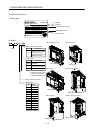
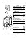
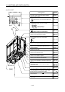
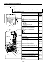
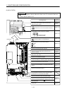
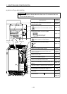
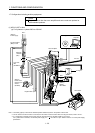
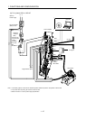
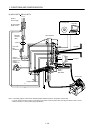
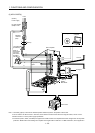
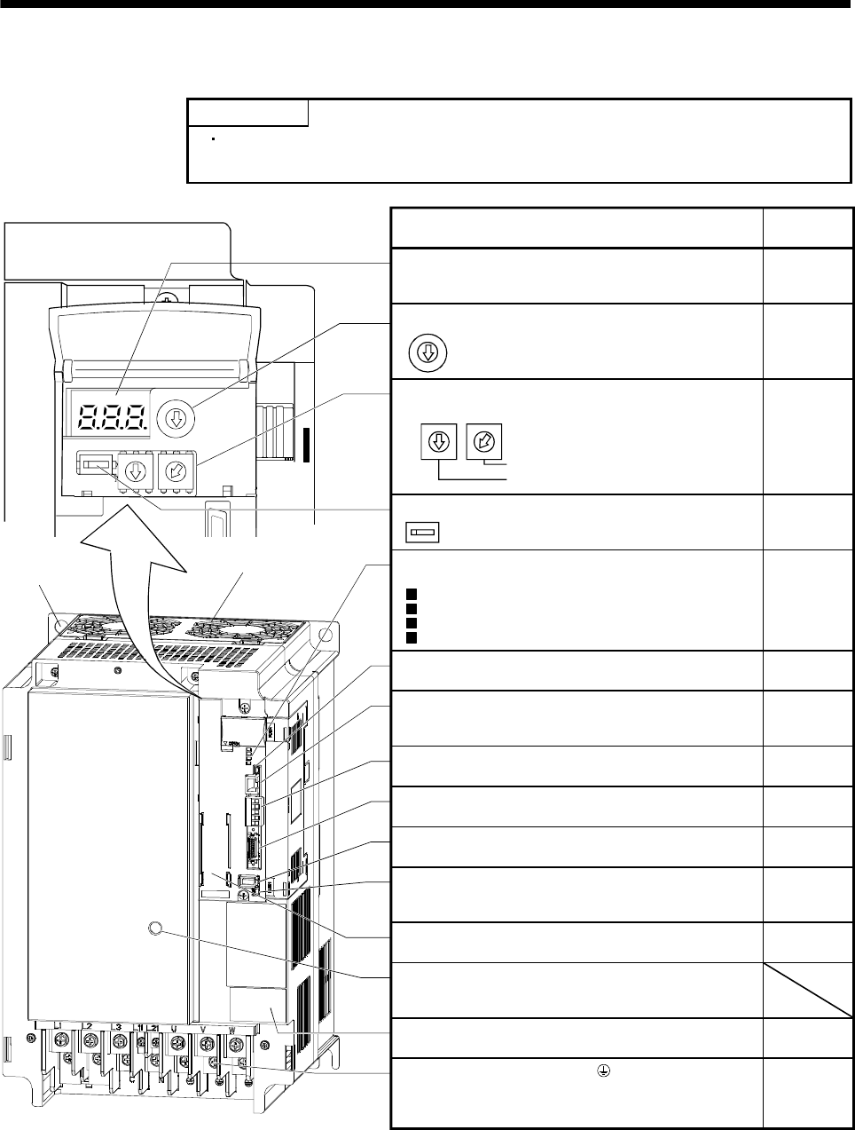
(6) MR-J3-11KT(4) to MR-J3-22KT(4)
POINT
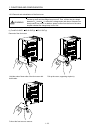
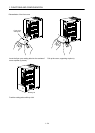
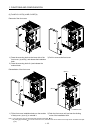
The servo amplifier is shown without the front cover. For removal of the front
cover, refer to section 1.6.2.
5
4
3
2
1
0
9
8
7
6
5
4
3
2
1
0
9
8
7
6
5
4
3
2
1
0
9
8
7
6
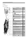
Fixed part
(4 places)
Cooling fan
Charge lamp
Lit to indicate that the main circuit is charged. While
this lamp is lit, do not reconnect the cables.
RS-422 communication connector (CN3)
Used to connect the MR-PRU03 parameter unit or
personal computer.
L.RUN
SD
RD
L.ERR
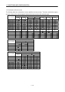
Set the number of occupied stations.
Station number switches (STATION NO.)
Set the station number of the servo amplifier.
Baud rate switch (MODE)
CC-Link connector (CN1)
Wire the CC-Link cable.
Communication alarm display section
Indicates alarms in CC-Link communication.
Select the CC-Link communication baud rate.
Occupied station count switch (SW1)
5
4
3
2
1
0
9
8
7
6
MODE
Set the ten place.
Set the one place.
5
4
3
2
1
0
9
8
7
6
5
4
3
2
1
0
9
8
7
6
X10 STATION NO. X1
SW1
Display
The 3-digit, seven-segment LED shows the servo
status and alarm number.
USB communication connector (CN5)
Used to connect the personal computer.
I/O signal connector (CN6)
Used to connect digital I/O signals.
Encoder connector (CN2)
Used to connect the servo motor encoder.
Battery connector (CN4)
Used to connect the battery for absolute position data
backup.
Battery holder
Contains the battery for absolute position data backup.
Rating plate
Protective earth (PE) terminal ( )
Ground terminal.
Name/Application
Detailed
explanation
Section 5.3
Chapter 11
Section 3.2.4
Section 3.2.3
Section 3.2.5
Section 11.3
Chapter 7
Chapter 7
Chapter 8
Chapter 15
Section 3.2.2
Section 4.2
Section 4.4
Section 4.10
Section 14.1
Section 5.8
Section 14.7
Section 5.8
Section 1.4
Section 4.1
Section 4.3
Section 12.1
Section 14.11