


3 - 9
3. CC-LINK COMMUNICATION FUNCTIONS
3.5 I/O signals (I/O devices) transferred to/from the programmable controller CPU
3.5.1 I/O signals (I/O devices)
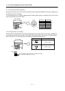
The input signals (input devices) may be used as either the CC-Link or CN6 external input signals. Make
selection in parameter No.PD06 to PD11, PD12 and PD14. The output signals (output devices) can be used as
both the CC-Link
CN6 external output signals.
POINT
In the factory-shipped status, the forward rotation stroke end (LSP), reverse
rotation stroke end (LSN) and proximity dog (DOG) are valid as the CN6
external input signals.
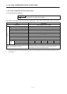
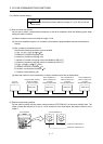
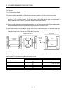
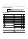
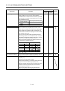
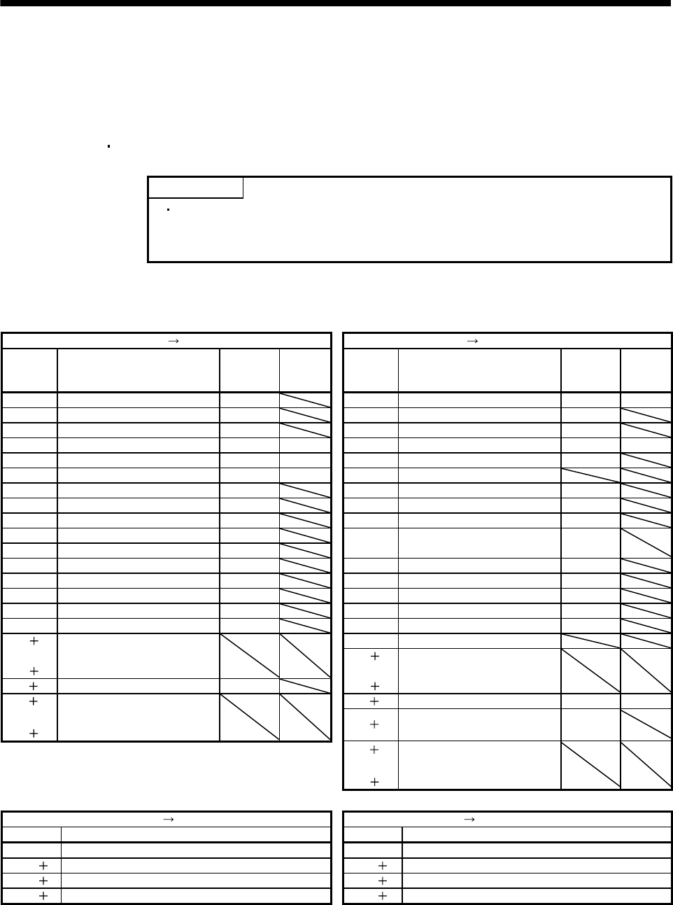
(1) When 1 station is occupied
RYn/RXn: 32 points each, RWrn/RWwn: 4 points each
Programmable controller Servo amplifier (RYn) Servo amplifier Programmable controller (RXn)
(Note)
Device No.
Signal name
Signal
abbreviation
CN6
connector
pin No.
(Note)
Device No.
Signal name
Signal
abbreviation
CN6
connector
pin No.
RYn0 Servo-on SON RXn0 Ready RD 14
RYn1 Forward rotation start ST1 RXn1 In position INP
RYn2 Reverse rotation start ST2 RXn2 Rough match CPO
RYn3 Proximity dog DOG 2 RXn3 Home position return completion ZP 16
RYn4 Forward rotation stroke end LSP 3 RXn4 Limiting torque TLC
RYn5 Reverse rotation stroke end LSN 4 RXn5 Reserved
RYn6 Automatic/manual selection MDO RXn6 Electromagnetic brake interlock MBR
RYn7 Temporary stop/Restart TSTP RXn7 Temporary stop PUS
RYn8 Monitor output execution demand MOR RXn8 Monitoring MOF
RYn9 Instruction code execution demand COR
RYnA Point table No. selection 1 DI0
RXn9
Instruction code execution
completion
COF
RYnB Point table No. selection 2 DI1 RXnA Warning WNG
RYnC Point table No. selection 3 DI2 RXnB Battery warning BWNG
RYnD Point table No. selection 4 DI3 RXnC Movement completion MEND
RYnE Point table No. selection 5 DI4 RXnD Dynamic brake interlock DB
RYnF Clear CR RXnE Position range output POT
RY(n 1)0 RXnF Reserved
to Reserved RX(n 1)1
RY(n 1)9
to Reserved
RY(n 1)A Reset RES RX(n 1)9
RY(n 1)B RX(n 1)A Trouble ALM 15
to Reserved
RY(n 1)F
RX(n
1)B
Remote station communication
ready
CRD
RX(n 1)C
to Reserved
RX(n 1)F
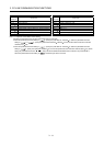
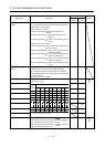
Programmable controller Servo amplifier (RWwn) Servo amplifier Programmable controller (RWrn)
Address No. Signal name Address No. Signal name
RWwn Monitor 1 RWrn Monitor 1 data
RWwn 1 Monitor 2 RWrn 1 Monitor 2 data
RWwn 2 Instruction code RWrn 2 Respond code
RWwn 3 Writing data RWrn 3 Reading data
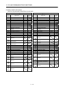
Note. "n" depends on the station number setting.