


6 - 3
6. PARAMETERS
6.1.3 Selection of command system
Parameter
No. Symbol Name
Initial
value
Unit Setting range
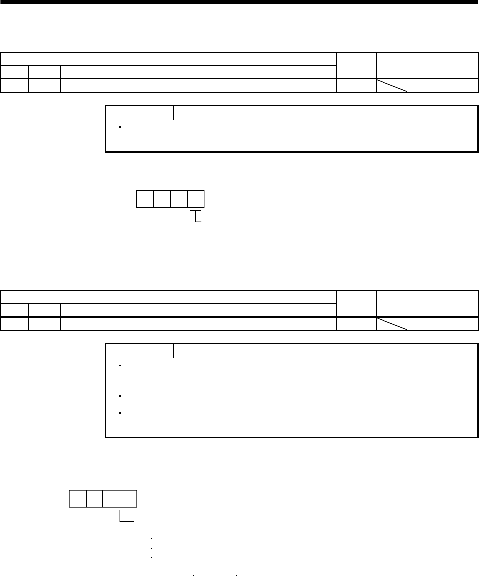
PA01 *STY Control mode 0000h Refer to the text.
POINT
This parameter is made valid when power is switched off, then on after
setting.
Select the command system.
Selection of command system
(Refer to section 5.4)
0: Absolute value command system
1: Incremental value command system
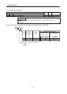
000
Parameter No.PA01
6.1.4 Selection of regenerative option
Parameter
No. Symbol Name
Initial
value
Unit Setting range
PA02 *REG Regenerative option 0000h Refer to the text.
POINT
This parameter is made valid when power is switched off, then on after
setting.
Wrong setting may cause the regenerative option to burn.
If the regenerative option selected is not for use with the servo amplifier,
parameter error (A37) occurs.
Set this parameter when using the regenerative option, brake unit, power regeneration converter, or power
regeneration common converter.
Selection of regenerative option
00: Regenerative option is not used
For servo amplifier of 100W, regenerative resistor is not used.
For servo amplifier of 200 to 7kW, built-in regenerative resistor is used.
Supplied regenerative resistors or regenerative option is used with
the servo amplifier of 11k to 22kW.
01: FR-BU2-(H) FR-RC-(H) FR-CV-(H)
02: MR-RB032
03: MR-RB12
04: MR-RB32
05: MR-RB30
06: MR-RB50(Cooling fan is required)
08: MR-RB31
09: MR-RB51(Cooling fan is required)
80: MR-RB1H-4
81: MR-RB3M-4(Cooling fan is required)
82: MR-RB3G-4(Cooling fan is required)
83: MR-RB5G-4(Cooling fan is required)
84: MR-RB34-4(Cooling fan is required)
85: MR-RB54-4(Cooling fan is required)
FA: When the supplied regenerative resistor is cooled by the cooling
fan to increase the ability with the servo amplifier of 11k to 22kW.
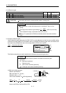
00
Parameter No.PA02