


38 DL-V3 User Manual Rev 3
Chapter 2 Installation and Setup
Occupation Time
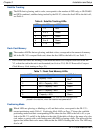
The LED that is glowing green corresponds to the DL-V3’s occupation time gauge. The
occupation time LEDs provide an indication of whether sufficient data has been collected for
successfully post processing data for the indicated baseline. The LED that appears corresponds
to the baseline length that you can process your data to, where the first LED to the left is #1. The
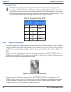
occupation time gauge has the following values from left to right, see Table 9:
Table 9: Occupation Time LEDs
2.2.4 External Oscillator
For certain applications requiring greater precision than what is possible using the on-board 20 MHz,
voltage-controlled, temperature-compensated crystal oscillator (VCTCXO), you may wish to connect
the DL-V3 to an external, high-stability oscillator. The external oscillator can be either 5 MHz or 10
MHz.
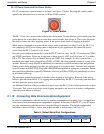
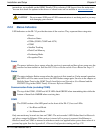
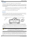
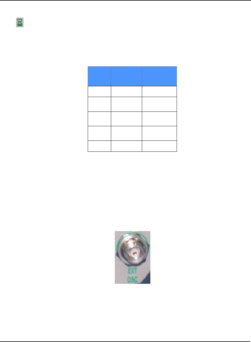
Operation consists of connecting a cable from the external oscillator to the DL-V3’s BNC external
oscillator port, labelled EXT OSC on the back of the DL-V3. See Figure 14 below. The receiver does
not have to be powered down during this procedure.
Figure 14: External Oscillator Port
Once the external oscillator has been installed, the EXTERNALCLOCK command (refer to the
OEMV Family Firmware Reference Manual) must be issued to define the clock model (for example,
cesium, rubidium or ovenized crystal). If the input clock rate is 5 MHz, the EXTERNALCLOCK
command must be issued to change the 10 MHz default rate.
LED#
Baseline
Length
(km)
LED Color
1
≤ 5
Green
2
> 5
≤ 10
Green
3
> 10
≤ 15
Green
4
> 15
≤ 20
Green
5
≥ 20
Green