


4 - 16
4. OPERATION AND DISPLAY
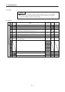
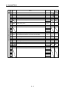
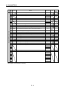
4.3.5 Drive unit parameter mode
The parameter setting of the drive unit is the same as that of the interface unit. Refer to Section 4.2.5.
To use the expansion parameters, change the setting of DRU parameter No. 19 (parameter write disable).
Refer to section 5.1.1.
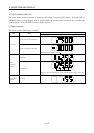
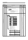
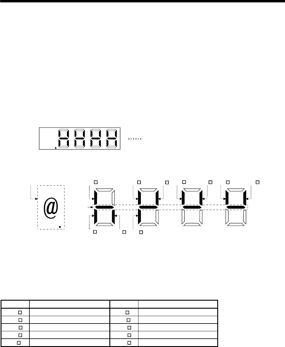
4.3.6 Drive unit external input signal display
The ON/OFF states of the digital input signals connected to the servo amplifier can be confirmed.
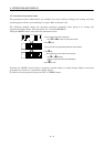
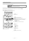
(1) Operation
Call the display screen shown after power-on.
Using the "MODE" button, show the diagnostic screen.
@
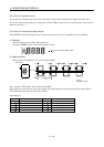
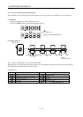
External input signal display screen
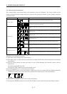
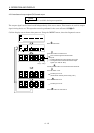
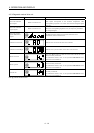
(2) Display definition
Corresponds to the signals of the seven-segment LED.
TL1 PC
CR
RES
SON LSN LSP
CM2
CM1 CDP
Slot number
Always lit
Lit: ON
Extinguished: OFF
The 7-segment LED shown above indicates ON/OFF.
Each segment at top indicates the input signal and each segment at bottom indicates the output signal.
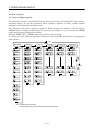
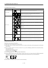
The following table indicates the signal names.
Signal Name List
Signal Signal Name Signal Signal Name
LSP Forward rotation stroke end PC Proportion control
LSN Reverse rotation stroke end TL1 Internal torque limit selection
SON Servo-on CM1 Electronic gear 1 selection
RES Reset CM2 Electronic gear 2 selection
CR Clear CDP Gain switch selection