


12 - 5
12. OPTIONS AND AUXILIARY EQUIPMENT
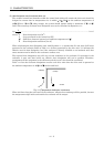
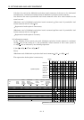
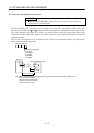
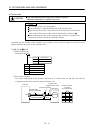
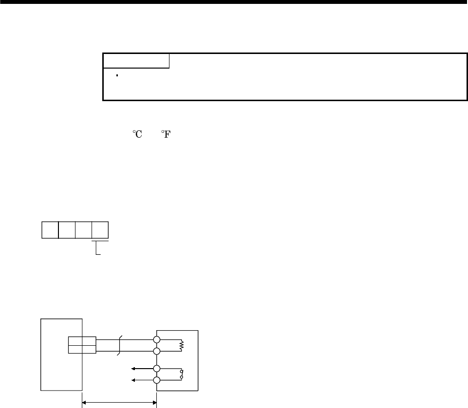
(3) Connection of the regenerative brake option
POINT
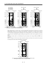
When using the MR-RB54, cooling by a fan is required. Please obtain a
cooling fan at your discretion.
Set IFU parameter No.1 according to the option to be used. The regenerative brake option will
generate heat of about 100
(212 )
. Fully examine heat dissipation, installation position, used cables,
etc. before installing the option. For wiring, use flame-resistant cables and keep them clear of the
regenerative brake option body. Always use twisted cables of max. 5m(16.4ft) length for connection
with the base unit.
The G3 and G4 terminals act as a thermal sensor. G3-G4 are disconnected when the regenerative
brake option overheats abnormally.
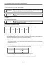
DRU parameter No.2
Selection of regenerativ
e
0: Not used.
2: MR-RB032
5: MR-RB14
6: MR-RB34
7: MR-RB54
3
P
C
G3
G4
2P
C
Base unit
Regenerative brake option
Note. Make up a sequence which will switch off the magnetic contactor (MC) when abnormal heating occurs.
G3-G4 contact specifications
Maximum voltage: 120V AC/DC
Maximum current: 0.5V/4.8VDC
Maximum capacity: 2.4V
A
5m (16.4 ft) max.
(Note)
CNP1A