


3 - 12
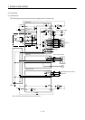
3. SIGNALS AND WIRING
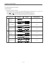
(b) Connections and waveforms
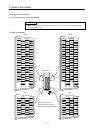
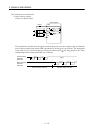
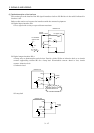
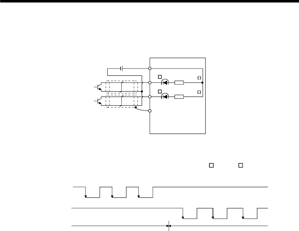
1) Open collector system
Connect as shown below:
SD
OPC
24VDC
Servo amplifier
NP
PP
Approx. 1.2k
Approx. 1.2k
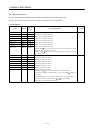
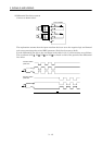
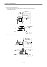
The explanation assumes that the input waveform has been set to the negative logic and forward
and reverse rotation pulse trains (DRU parameter No.21 has been set to 0010). The waveforms
in the table in (a), (1) of this section are voltage waveforms of PP
and NP based on SG. Their
relationships with transistor ON/OFF are as follows:
(ON)
(OFF)
(ON)
(ON) (OFF) (ON) (OFF) (ON)(OFF)
(OFF)(ON)
Forward rotation
pulse train
(transistor)
Reverse rotation
pulse train
(transistor)
Forward rotation command Reverse rotation command
(OFF)