


12 - 3
12. OPTIONS AND AUXILIARY EQUIPMENT
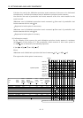
(b) To make selection according to regenerative energy
Use the following method when regeneration occurs continuously in vertical motion applications or
when it is desired to make an in-depth selection of the regenerative brake option:
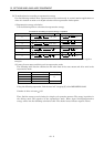
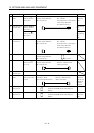
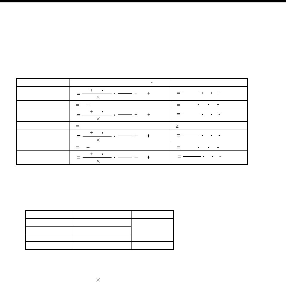
1) Regenerative energy calculation
Use the following table to calculate the regenerative energy.
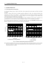
Formulas for calculating torque and energy in operation
Regenerative power Torque applied to servo motor [N m] Energy [J]
1)
T1
(JL JM)
9.55
10
4
No
1
Tpsa1
TU
T
F
E
1
2
0.1047
No
T
1
T
psa1
2) T
2
T
U
T
F
E
2
0.1047 No T
2
t
1
3)
T
3
(JL JM)
9.55
10
4
No
1
T
psd1
TU TF
E
3
2
0.1047
No
T
3
T
psd1
4), 8) T
4
T
U
E
4
0 (No regeneration)
5)
T
5
(JL JM)
9.55
10
4
No
1
T
psa2
TU TF
E
5
2
0.1047
No
T
5
T
psa2
6) T
6
T
U
T
F
E
6
0.1047 No T
6
t
3
7)
T
7
(JL JM)
9.55
10
4
No
1
T
psd2
TU TF
E
7
2
0.1047
No
T
7
T
psd2
From the calculation results in 1) to 8), find the absolute value (Es) of the sum total of negative
energies.
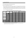
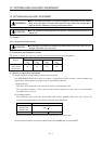
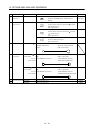
2) Losses of servo motor and drive unit in regenerative mode
The following table lists the efficiencies and other data of the servo motor and drive unit in the
regenerative mode.
Drive unit Inverse efficiency [%] C charging [J]
MR-J2M-10DU 55
MR-J2M-20DU 70
MR-J2M-40DU 85
5.5
MR-J2M-70DU 80 18
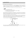
Using the following expression, find the total of C charging [J] of the MELSERVO-J2M.
Number of drive unit axes
5.5J
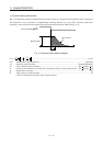
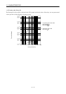
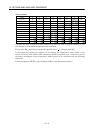
Then, find the energy at each timing in a single-cycle operation pattern. The energy is positive in
the driving mode and negative in the regenerative mode. Enter signed driving/regenerative
energy values into the following calculation table. The shaded areas indicate negative values.