


3 - 10
3. SIGNALS AND WIRING
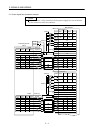
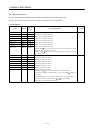
(3) Communication
POINT
Refer to Chapter 13 for the communication function.
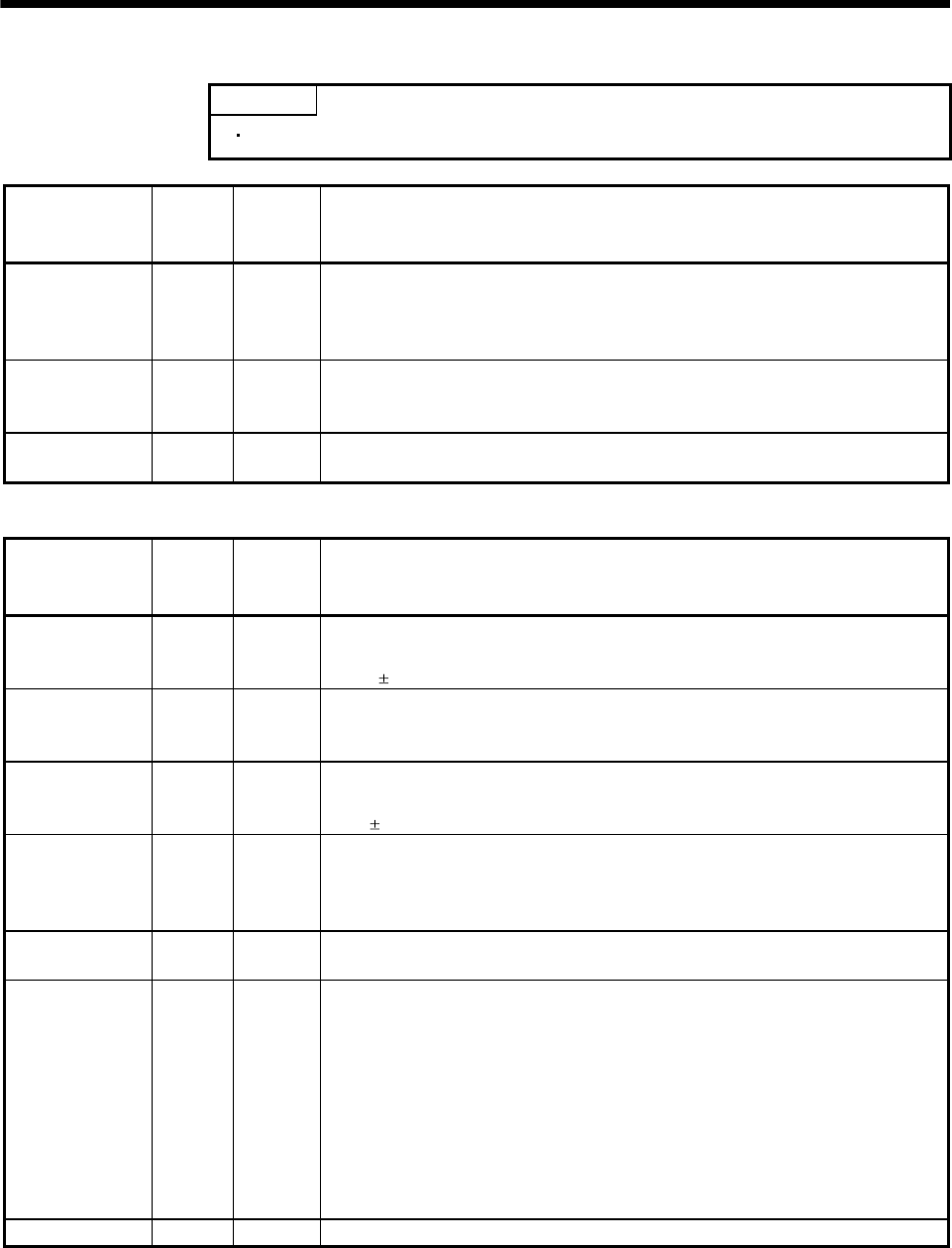
Signal Symbol
Connector
pin No.
Functions/Applications
RS-422 I/F SDP
SDN
RDP
RDN
CN3-9
CN3-19
CN3-5
CN3-15
RS-422 and RS-232C functions cannot be used together.
Choose either one in IFU parameter No. 16.
RS-422
termination
TRE CN3-10 Termination resistor connection terminal of RS-422 interface.
When the servo amplifier is the termination axis, connect this terminal to RDN
(CN3-15).
RS-232C I/F RXD
TXD
CN3-2
CN3-12
RS-422 and RS-232C functions cannot be used together.
Choose either one in IFU parameter No. 0.
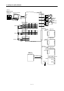
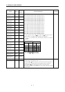
(4) Power supply
Signal Symbol
Connector
pin No.
Functions/Applications
Digital I/F power
supply input
VIN CN1A-26
CN1B-26
Driver power input terminal for digital interface.
Input 24VDC (300mA or more) for input interface.
24VDC
10%
Digital I/F
common
SG CN1A-1
CN1B-1
CN5-8
Common terminal of VIN. Pins are connected internally.
Separated from LG.
5V output P5 CN1A-49
CN1B-49
CN3-20
Internal power supply for encoder Z-phase pulses. Connect P5-OP_VIN when using
this power supply as an encoder Z-phase pulse common.
5VDC
5%
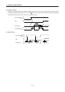
Encoder Z-phase
pulse power
supply
OP_VIN CN1A-47
CN1B-47
Power input for encoder Z-phase pulse common. Connect P5-OP_VIN when using
the 5V output (P5) as an encoder Z-phase pulse common. Supply power to OP_VIN
when using an external power supply as an encoder Z-phase pulse common. At this
time, do not connect P5-OP_VIN.
Encoder Z-phase
pulse common
OP_COM
CN1A-48
CN1B-48
Common for encoder Z-phase pulses. Power input to OP_VIN is output from
OP_COM.
Control common LG CN1A-50
CN1A-46
CN1A-21
CN1B-50
CN1B-46
CN1B-21
CN3-1
CN3-3
CN3-11
CN3-13
Common terminal for MO1, MO2 and MO3.
Shield SD Plate Connect the external conductor of the shield cable.