


3 - 9
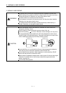
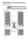
3. SIGNALS AND WIRING
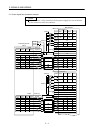
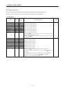
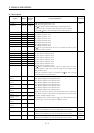
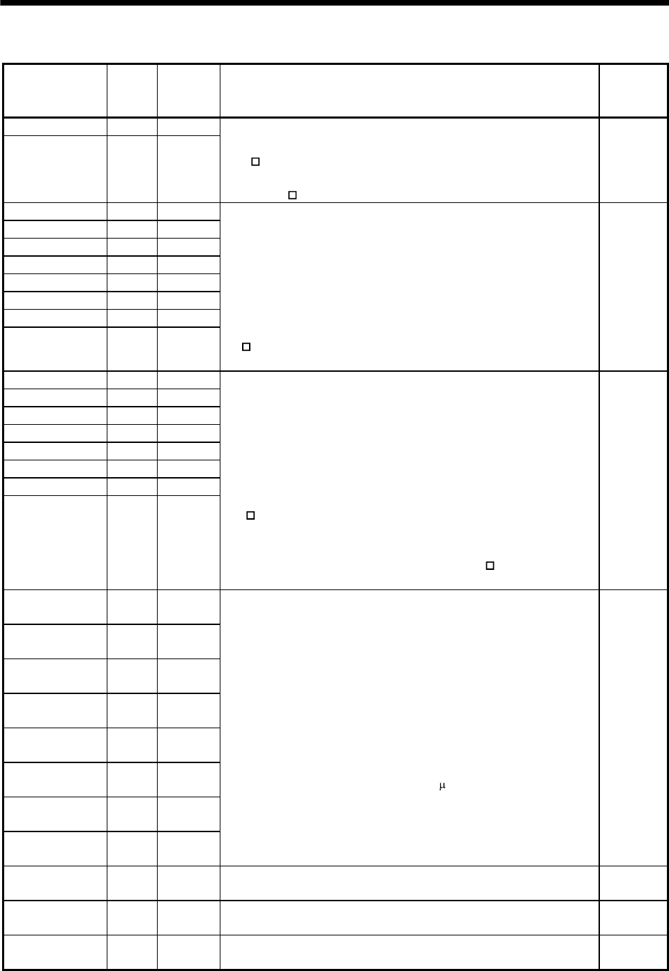
(2) Output signals
Signal Symbol
Connector
pin No.
Functions/Applications I/O division
Trouble A ALM_A CN1A-27
Trouble B ALM_B CN1B-27
ALM_A: Alarm signal for slot 1 to 4
ALM_B: Alarm signal for slot 5 to 8
ALM
-SG are disconnected when power is switched off or the
protective circuit is activated to shut off the base circuit. Without
alarm, ALM
-SG are connected within about 3s after power on.
DO-1
Ready 1 RD 1 CN1A-11
Ready 2 RD 2 CN1A-33
Ready 3 RD 3 CN1A-6
Ready 4 RD 4 CN1A-28
Ready 5 RD 5 CN1B-11
Ready 6 RD 6 CN1B-33
Ready 7 RD 7 CN1B-6
Ready 8 RD 8 CN1B-28
RD 1: Ready signal for slot 1
RD 2: Ready signal for slot 2
RD 3: Ready signal for slot 3
RD 4: Ready signal for slot 4
RD 5: Ready signal for slot 5
RD 6: Ready signal for slot 6
RD 7: Ready signal for slot 7
RD 8: Ready signal for slot 8
RD
-SG are connected when the servo is switched on and the servo
amplifier is ready to operate.
DO-1
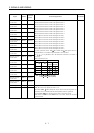
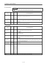
In position 1 INP 1 CN1A-35
In position 2 INP 2 CN1A-8
In position 3 INP 3 CN1A-30
In position 4 INP 4 CN1A-3
In position 5 INP 5 CN1B-35
In position 6 INP 6 CN1B-8
In position 7 INP 7 CN1B-30
In position 8 INP 8 CN1B-3
INP 1: In position signal for slot 1
INP 2: In position signal for slot 2
INP 3: In position signal for slot 3
INP 4: In position signal for slot 4
INP 5: In position signal for slot 5
INP 6: In position signal for slot 6
INP 7: In position signal for slot 7
INP 8: In position signal for slot 8
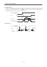
INP
-SG are connected when the number of droop pulses is in the
preset in-position range. The in-position range can be changed using
DRU parameter No. 5.
When the in-position range is increased, INP
-SG may be kept
connected during low-speed rotation.
DO-1
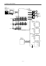
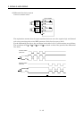
Encoder Z-phase
pulse 1
OP 1 CN1A-25
Encoder Z-phase
pulse 2
OP 2 CN1A-24
Encoder Z-phase
pulse 3
OP 3 CN1A-23
Encoder Z-phase
pulse 4
OP 4 CN1A-22
Encoder Z-phase
pulse 5
OP 5 CN1B-25
Encoder Z-phase
pulse 6
OP 6 CN1B-24
Encoder Z-phase
pulse 7
OP 7 CN1B-23
Encoder Z-phase
pulse 8
OP 8 CN1B-22
OP 1: Encoder Z-phase pulse signal for slot 1
OP 2: Encoder Z-phase pulse signal for slot 2
OP 3: Encoder Z-phase pulse signal for slot 3
OP 4: Encoder Z-phase pulse signal for slot 4
OP 5: Encoder Z-phase pulse signal for slot 5
OP 6: Encoder Z-phase pulse signal for slot 6
OP 7: Encoder Z-phase pulse signal for slot 7
OP 8: Encoder Z-phase pulse signal for slot 8
Outputs the zero-point signal of the encoder. One pulse is output per
servo motor revolution. OP and LG are connected when the zero-point
position is reached. (Negative logic)
The minimum pulse width is about 400
s. For home position return
using this pulse, set the creep speed to 100r/min. or less.
DO-2
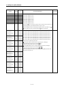
Analog monitor 1 MO1 CN3-4 Used to output the data set in IFU parameter No.3 (Analog monitor 1
output) to across MO1-LG in terms of voltage. Resolution 10 bits
Analog
output
Analog monitor 2 MO2 CN3-14 Used to output the data set in IFU parameter No.4 (Analog monitor 2
output) to across MO2-LG in terms of voltage. Resolution 10 bits
Analog
output
Analog monitor 3 MO3 CN3-7 Used to output the data set in IFU parameter No.5 (Analog monitor 3
output) to across MO3-LG in terms of voltage. Resolution 10 bits
Analog
output