


5 - 9
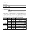
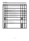
5. PARAMETERS
Class No. Symbol Name and function
Initial
value
Unit
Setting
range
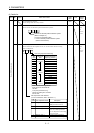
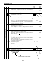
28 TL1
Internal torque limit 1
Set this parameter to limit servo motor torque on the assumption that the
maximum torque is 100[%].
When 0 is set, torque is not produced.
When torque is output in analog monitor, this set value is the maximum
output voltage (
4V). (Refer to Section 3.3.5 (2))
100 % 0
to
100
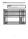
29 0
30 0
31 0
32
For manufacturer setting
Do not change this value any means.
0
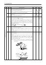
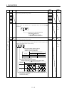
33 MBR Electromagnetic brake sequence output
Used to set the delay time (Tb) between electronic brake interlock (MBR
)
and the base drive circuit is shut-off.
100 ms 0
to
1000
34 GD2 Ratio of load inertia moment to servo motor inertia moment
Used to set the ratio of the load inertia moment to the servo motor shaft
inertia moment. When auto tuning mode 1 and interpolation mode is
selected, the result of auto tuning is automatically used.
(Refer to section 6.2.1)
In this case, it varies between 0 and 1000.
70 0.1
times
0
to
3000
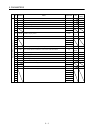
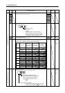
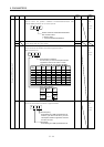
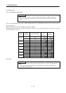
35 PG2 Position loop gain 2
Used to set the gain of the position loop.
Set this parameter to increase the position response to level load
disturbance. Higher setting increases the response level but is liable to
generate vibration and/or noise.
When auto tuning mode 1
2 and interpolation mode is selected, the result
of auto tuning is automatically used.
35 rad/s 1
to
1000
36 VG1 Speed loop gain 1
Normally this parameter setting need not be changed.
Higher setting increases the response level but is liable to generate
vibration and/or noise.
When auto tuning mode 1
2, manual mode and interpolation mode is
selected, the result of auto tuning is automatically used.
177 rad/s 20
to
8000
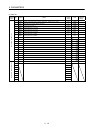
37 VG2 Speed loop gain 2
Set this parameter when vibration occurs on machines of low rigidity or
large backlash. Higher setting increases the response level but is liable to
generate vibration and/or noise.
When auto tuning mode 1
2 and interpolation mode is selected, the result
of auto tuning is automatically used.
817 rad/s 20
to
20000
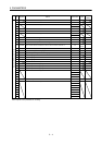
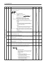
38 VIC Speed integral compensation
Used to set the integral time constant of the speed loop.
Lower setting increases the response level but is liable to generate vibration
and/or noise.
When auto tuning mode 1
2 and interpolation mode is selected, the result
of auto tuning is automatically used.
48 ms 1
to
1000
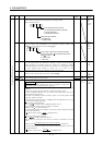
39 VDC Speed differential compensation
Used to set the differential compensation.
Made valid when the proportion control (PC
) is switched on.
980 0
to
1000
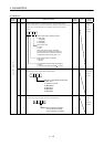
40 0
41
For manufacturer setting
Do not change this value any means.
0000
Expansion DRU parameters 1
42 *DI1 Input signal selection 1
Used to set the clear (CR
).
0 0
Clear (CR ) selection
0: Droop pulses are cleared on the leading edge.
1: While on, droop pulses are always cleared.
3
0003
Refer to
Name
and
function
column.