


1 - 9
1. FUNCTIONS AND CONFIGURATION
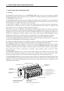
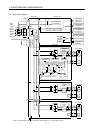
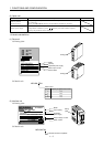
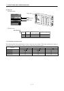
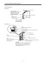
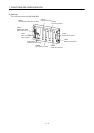
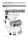
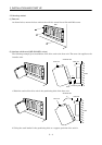
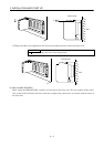
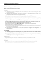
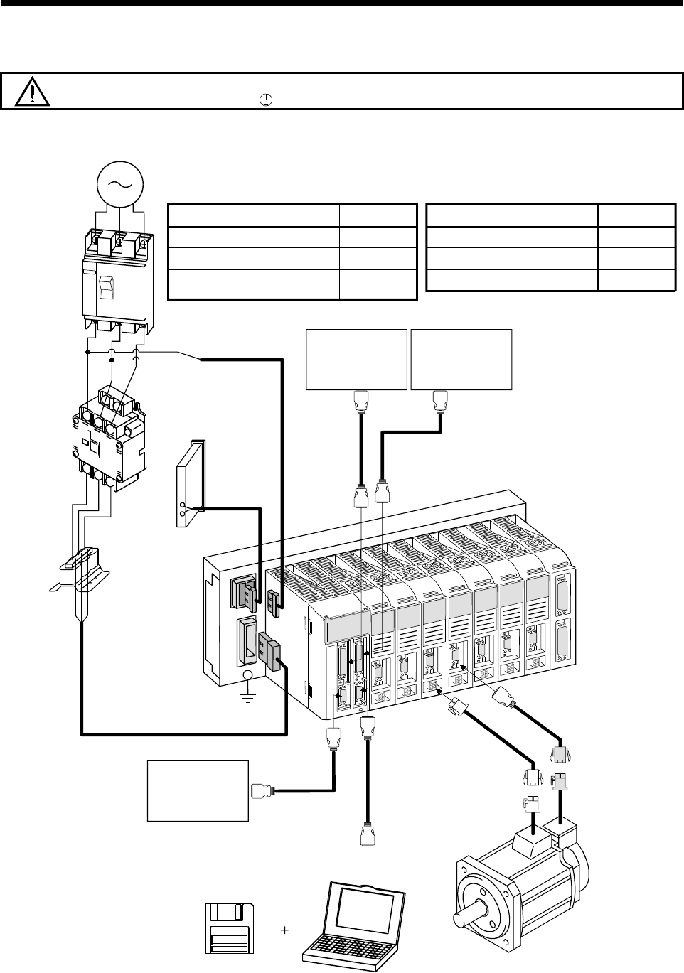
1.8 Servo system with auxiliary equipment
WARNING
To prevent an electric shock, always connect the protective earth (PE) terminal
(terminal marked
) of the base unit to the protective earth (PE) of the control box.
C
P
L2
L1
L
3
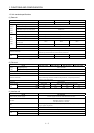
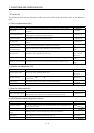
Options and auxiliary equipment
No-fuse breaker
Magnetic contactor
MR Configurator
(servo configuration software)
Regenerative brake option
Reference
Section 12.2.2
Section 12.2.2
Section 12.1.4
Section 12.1.1
Options and auxiliary equipment
Reference
Cables
Section 12.2.1
Power factor improving reactor
Section 12.2.3
3-phase 200V to 230VAC
power supply
(Note) 1-phase 200V to 230VAC
No-fuse
breaker
(NFB) or
fuse
Magnetic
contactor
(MC)
Powe
r
f
acto
r
improving
reacto
r
(FR-BAL)
MR Configurator
(servo configuration software
MRZJW3-SETUP151E or later)
Personal computer
Power supply lead
Encoder cable
Regenerative brake
option
L
21
L
11
Control circuit
power supply
To CNP1A
To CNP1B
To CN1A
To CN1B
Command device
(For 1 to 4 slots)
Command device
(For 5 to 8 slots)
To CNP3
To CN5
To CN3
Main circuit power supply
Note. For 1-phase 200 to 230VAC, connect the power supply to L1, L2 and leave L3 open.
Machine contact